
Home › Forums › SE England › Kent Mills A to F › Aylesford Paper Mills
Tagged: Case-making, Closed, MG machines, Newsprint
- This topic has 173 replies, 5 voices, and was last updated 1 year, 9 months ago by
Chris Bennett.
-
AuthorPosts
-
27th October 2021 at 10:41 #1424
Artless Bodger
Participant119. Switchboard.
This is located in the powerhouse, as seen in the background of photo 121.
Attachments:
27th October 2021 at 10:48 #1426Participant120. Main Drive Shaft.
This is the eastern section under the white beaterfloor, another shaft ran from the powerhouse under the kraft beaterfloor as the mill was extended, and can be seen in some of the mill plans. By the late 1970s the white beaterfloor basement had been extensively rebuilt aand no sign of the main shaft remained. Some support piers of the western section remained under the kraft beaterfloor near chests Y1 – Y4 (the vertical cylindrical chests then serving no 3 m/c and as a starch slurry tank). The underside of the upperfloor of the beaterfloors showed the arrangement of the steel beams to provide for the drive belts to pass through to the refiners and beaters.
Attachments:
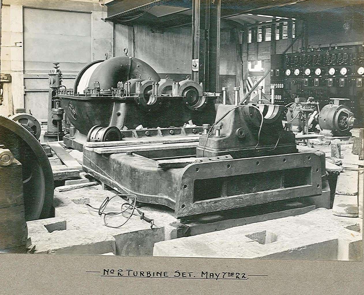
27th October 2021 at 11:07 #1428Participant121. No 2 Turbine Set.
The trubine is in place – the curved casing at the back, the steam control valve stand to its left. The open casing is for the reduction gearing, 3600 rpm to 428 rpm, to drive the generator (DC 400V) which would be installed on the cast bed frame centre. The gear casing has DBS – David Brown and Sons of Huddersfield, cast on it. In front of the genrator an extension drive shaft to a further reduction gearbox to reduce the speed to 150 rpm for the main shaft. The main shaft would pass through the sqaure hole in the wall, just visible top left, to the white beaterfloor basement. To the extreme left is visible a gear, probably part of the no 1 turbine set reduction gear to the main shaft. The turbines and generators stood side by side but the final drives to the main shaft were offset, see drawing AX107.
Attachments:
27th October 2021 at 11:11 #1430Participant122. Salle, Feb 1922.
This photo was taken from a position roughly in line with the future New Hythe Halt behind the photographer. The mill siding is visible in the foreground, such as it was then, later No 6 loading dock would occupy this area. The wooden huts and trees are those seen in the flood photos.
-
This reply was modified 4 years, 11 months ago by
Artless Bodger. Reason: Spelling
Attachments:
27th October 2021 at 11:24 #1433Participant123. No 2 Machine, May 1922.
Nearing completion, the deckle straps are in place, breast box under construction and the base for the 3 Fulner filters on the thin stock approach. This is much different to no 2’s condition when I knew it in the late ’70s – early ’80s. The breast box is low with less hydraulic head than it had later, so the machine speed would be relatively low (iirc it could do around 300mpm in the ’80s, i.e. around 9-10 tph at 125gsm). Six Fulner filters on the floor, 3 for each of nos 1 and 2. No 1’s eirw frame and table roll ends just visible lower RH corner.
Attachments:
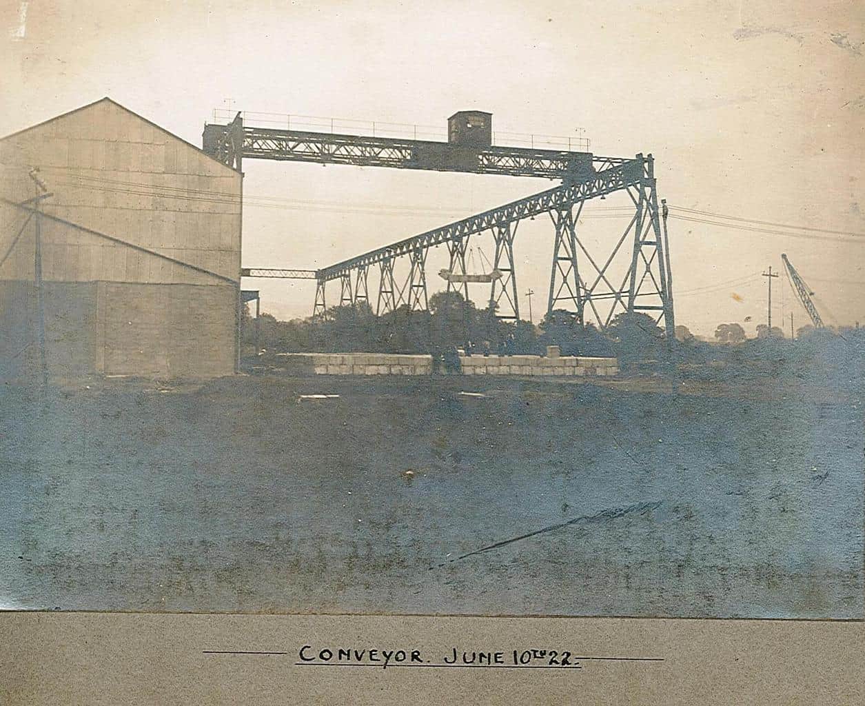
27th October 2021 at 11:27 #1435Participant124. Conveyor, June 1922.
Pulp stacks being built, the temporary corrugated iron upper wall to the powerhouse and beaterfloor range on the left, later opened up when the powerhouse was extended and the kraft beaterfloor constructed.
Attachments:
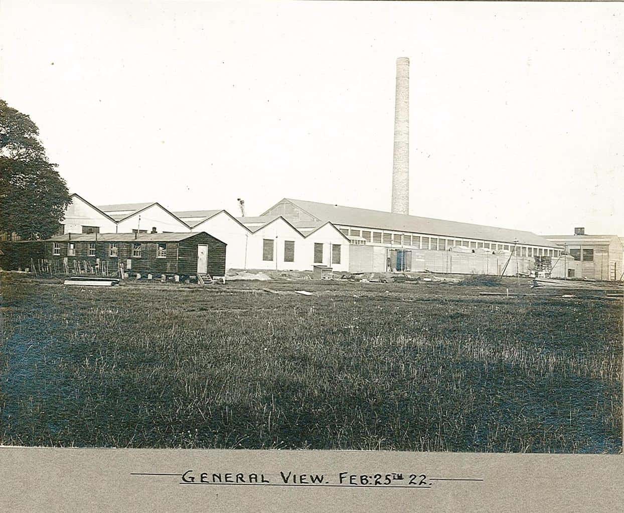
27th October 2021 at 11:32 #1437Participant125. General View, Feb 25, 1922.
The photographer must be standing with their back almost to New Hythe Lane level crossing. The temporary standard gauge siding to bring the machine parts into the end of the machine house can be seen rising centre left, to the opening left in the machine house wall.
That’s all folks!
But, some drawings will be provided later (too big to attach here). Also there are some photos taken during east mill demolition which I may post if there is sufficient interest.
Attachments:
7th February 2022 at 14:18 #1450Thejoker1969
ParticipantWould anyone happen to know if there are any books that have been written about Reeds Paper mill in Aylesford or any collection of info and photographs? I would like to buy something for my 95 year old grandad who worked at the mill between 1954 and 1984.
Please contact me directly on
07909 994973
Many thanks, Steve Drury
7th February 2022 at 16:26 #1451Chris Bennett
KeymasterHi Steve
There was a book published by Aylesford Newsprint in 1995 “A New Era in Papermaking” that covers some of the history.
THe links on https://ukpapermills.org.uk/topic/aylesford-paper-mills/ are worth exploring.Quite a few links further down on the page as well.
I have written about the mill during my time in https://ukpapermills.org.uk/wp-content/uploads/2017/12/20171209a-Aylesford-Paper-Mill-1974-81.pdf
and pictures about the effluent https://ukpapermills.org.uk/apm-effluent-1980-pictures/Happy to share the orginals if that helps you.
Hope this gets you started.
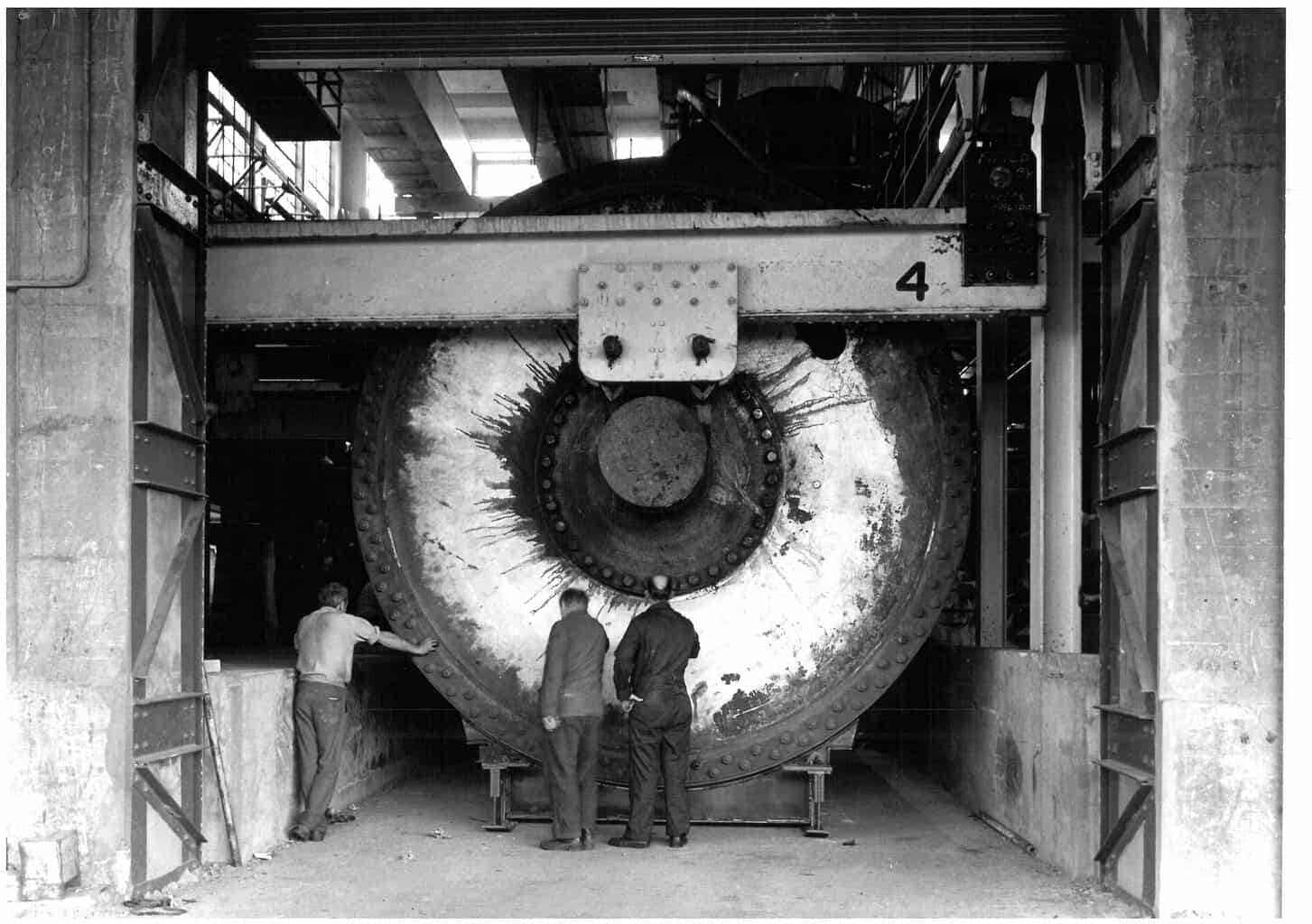
23rd December 2023 at 19:56 #1569ParticipantSome more photos that were scanned and sent to me when East Mill was demolished. Firstly the removal of an MG cylinder from East Mill nos 5,6,7,8 machine house. The caption says no 5 machine but I think it is too far down the length of no 6 on the right to be no 5 and is actually no 7. When I worked in the mill – 1975 – 1978 summers, 1978 – 1985 full time, no 5 machine was still extant, no 7 was a hole in the floor.
Attachments:
23rd December 2023 at 19:56 #1571ParticipantIn the dock, no 8 MG dryer hood in background.
Attachments:
23rd December 2023 at 19:58 #1573ParticipantThe cylinder being dragged out by the Wynns Heavy Haulage tractor. The tractor is a Scammell Contractor, the other lorry appears to be an AEC Matador or similar.
Attachments:
23rd December 2023 at 20:00 #1575ParticipantFinally the cylinder departs over New Hythe station level crossing, the brick building in the left background was demolished later to widen the junction of New Hythe Lane and Mill Hall Road, and a security office was built here.
-
This reply was modified 2 years, 9 months ago by
Attachments:
23rd December 2023 at 20:17 #1578ParticipantNo 10 machine rebuild, the machine initilly had just a single MG cylinder, like no 8, as shown in the attached plan. The reeler stood between the machine reel up and no 11’s screens. There is a photograph, on the English Heritage website I think, which shows no 10 in this condition with no 9 wet end beyond. At this time 10 had no pre-driers. It was later rebuilt (was it originally a tissue machine and with the construction of the KC mill and consumer choice changing to soft tilet tissue, reduced demand led to its rebuild? Pure speculation on my part at this stage, would be great to hear from someone who knows).
These photos show the removal of the old MG cylinder and the delivery and installation of the new cylinder.
WM plan showing original no 10 layout – undated.
Attachments:
23rd December 2023 at 20:18 #1580ParticipantNo 10 cropped from main plan.
Attachments:
-
AuthorPosts







- You must be logged in to reply to this topic.