Forum Replies Created
-
AuthorPosts
-
Artless Bodger
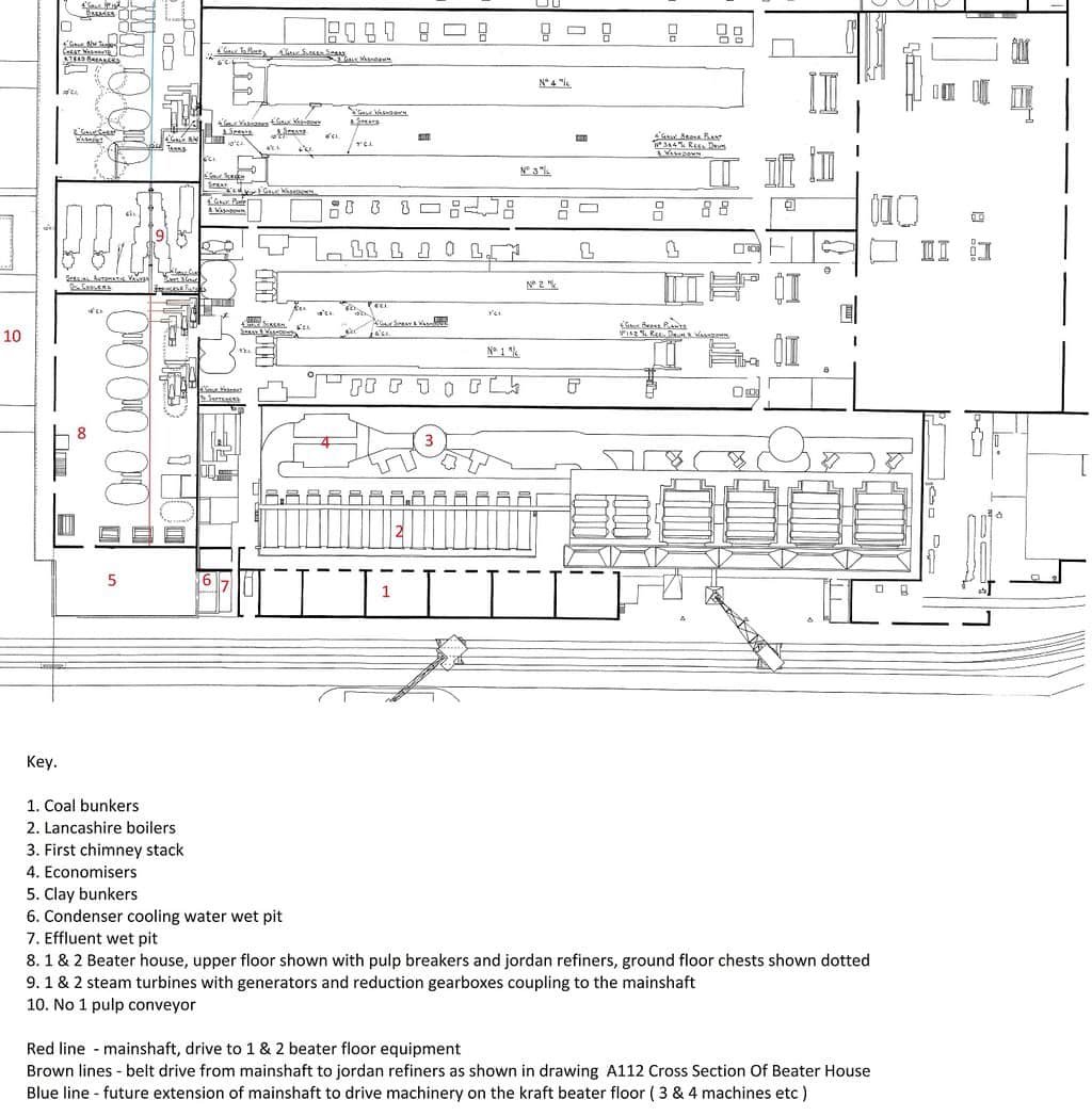
ParticipantExtract of old proc water bw to show changes to beaterfloor / turbine house noted in post 1318.
ParticipantCorrection, pdf too large to upload, will transfer separately.
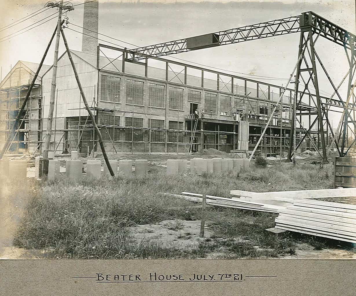
Participant73. Beater house 7/7/21
This view is notable for showing the temporary cladding for the west end of the beaterfloor section (as it was then) and the concrete wall to the powerhouse, both with openings left for temporary railway tracks to enter so that machinery could be brought in (visible in some later photos in this series). Several photos of the interior of the beaterfloor, and some external views such as this, show the beaterfloor extending past the original turbine house, though later on this extension was incorporated into the powerhouse – there was no internal access on the upper level from the white beaterfloor to the kraft beaterfloor, and this later arrangement is shown in the plan loaded next (old proc water bw).
The verandah or loading stage seen here was later extended with the construction of the kraft beaterfloor also the pulp conveyor.
Attachments:
Participant72. Centrifugal pump no 2 machine.
I’m assuming this is the fan pump – on 1 and 2 the fan pumps were situated in pits alongside the wet end, but in what was the end of the annexe, it does not appear clearly in any other photo in this series. The wire pit was different to that later employed for 2 and 3 when they were rebuilt. See the drawing AX411(? drawing number is very blurred and is added by Reed’s and dated 7/4/22? as it does not correspond to other AX drawing layouts, the number bottom left appears to be 35-1 dated Jan 1922 and reference to template pipes not supplied by C. W. & co, presumably the originators of the drawing).
Drawing uploaded separately as it exceeds the 700 KB limit.
Attachments:
ParticipantEast Mill 1-4 machines plan, annotated.
This is an extract from a plan dated sometime after the mid 30s when all the East Mill machines were in place, but before the rebuild of no 3 and the removal of no 4, so probably mid 50s.
Attachments:
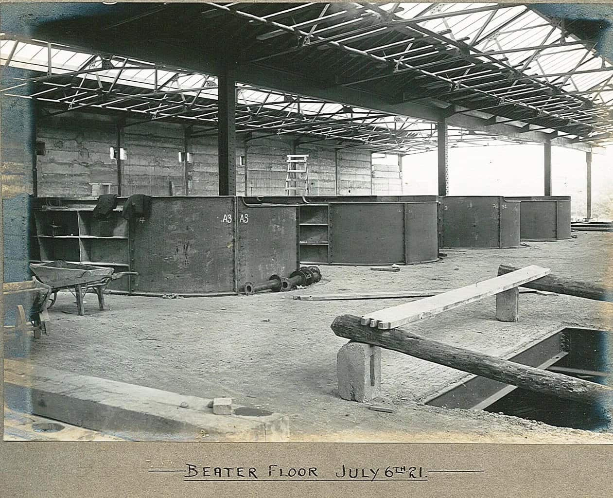
Participant70. Beaterfloor 6/7/21.
Looking out towards the river, with the 4 breaker tubs in place, as shown on the plan.
Attachments:
Participant71. Floor over basement 2.
Out of sequence from the folder but follows on from the above no 69. Taken from approximately the position of no 2’s reel up (as built), showing the conrete foundations for the supercalender. NG track in the centre leading to the service tunnel. On the right under the floor steelwork is the shuttering for the broke potcher. This had been removed by my time but the corresponding one for no 4 mc was still extant (though the machine was long gone) in 3/4 basement, along with its duplex stock pump.
Attachments:
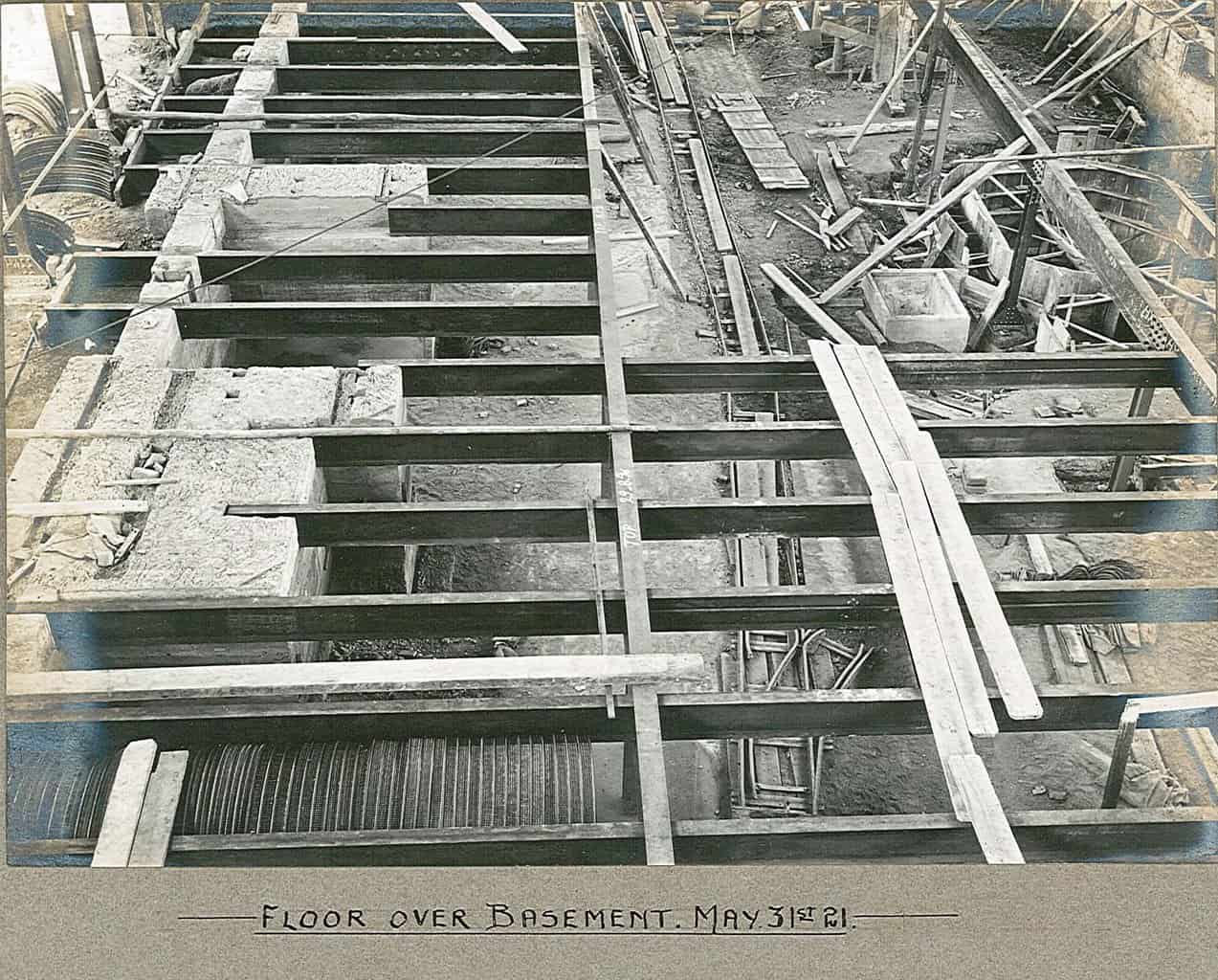
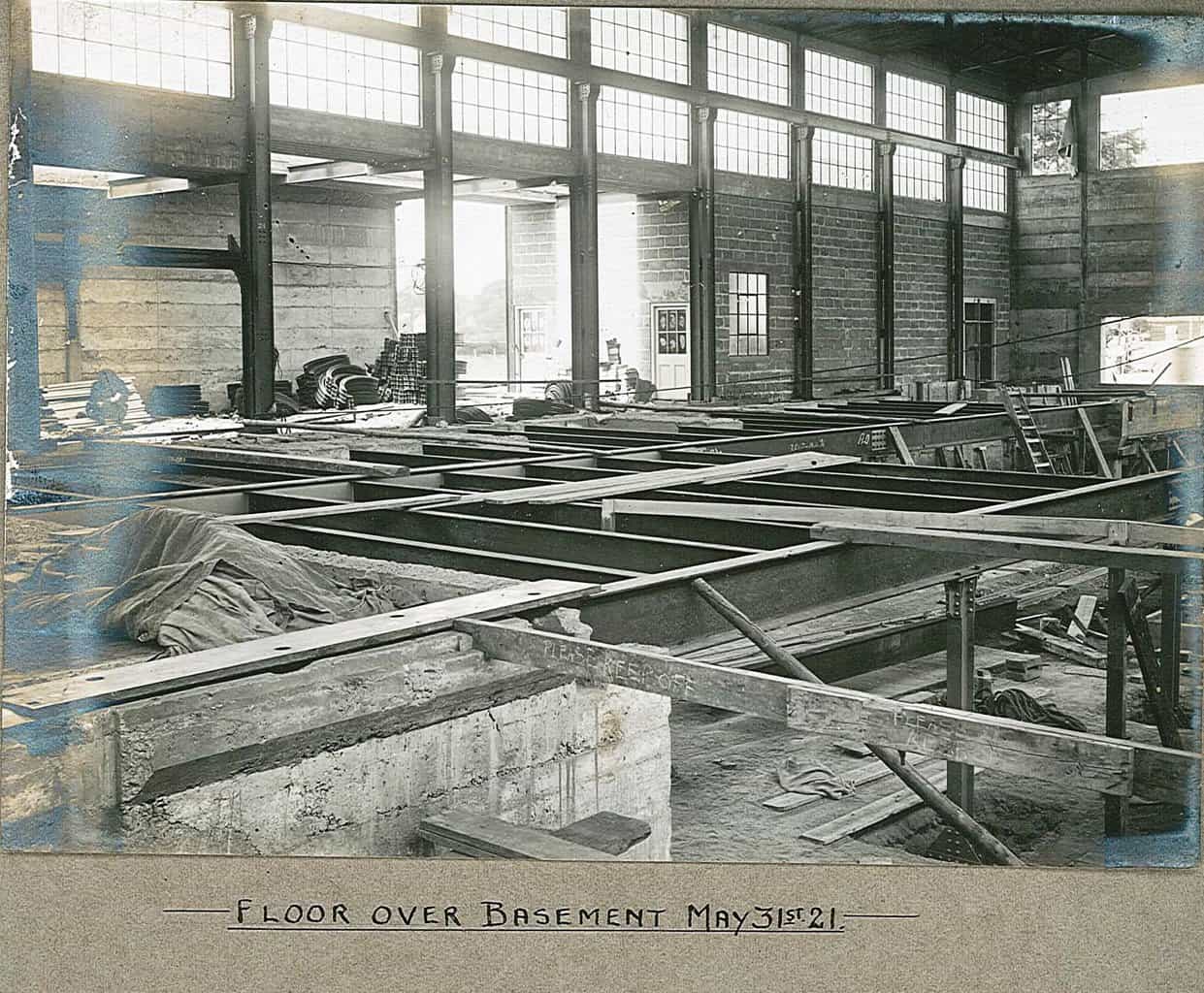
Participant69. Floor over basement 31/5/21.
The photo is taken from the end of 1 mc whose soleplates are visible in the foreground. The NG track leading into the service tunnel can just be made out, and the tops of the concrete foundations for 2 mc supercalender. Stacks of Hi-rib ready to carry the vaulting over the basement here, an area know to some in my time as ‘Piccadily Circus’, it later housed the solvo pulper for 2 mc reel up after the 1975 rebuild, the starch tanks for the size press and some device for oil / water separation (part of the lubrication system? Alfa-Laval?).
Attachments:
Participant68. Machine house 31/5/21.
A view looking south – to the machine wet ends, the sole plates for both machines are in place, the service tunnel is roofed over except for the far end, where the NG track can be seen. Shuttering in place for the floor drain gulley along the front side of 2 mc. Hot air duct outlets visible under the ceiling, which now appears to be complete.
Attachments:
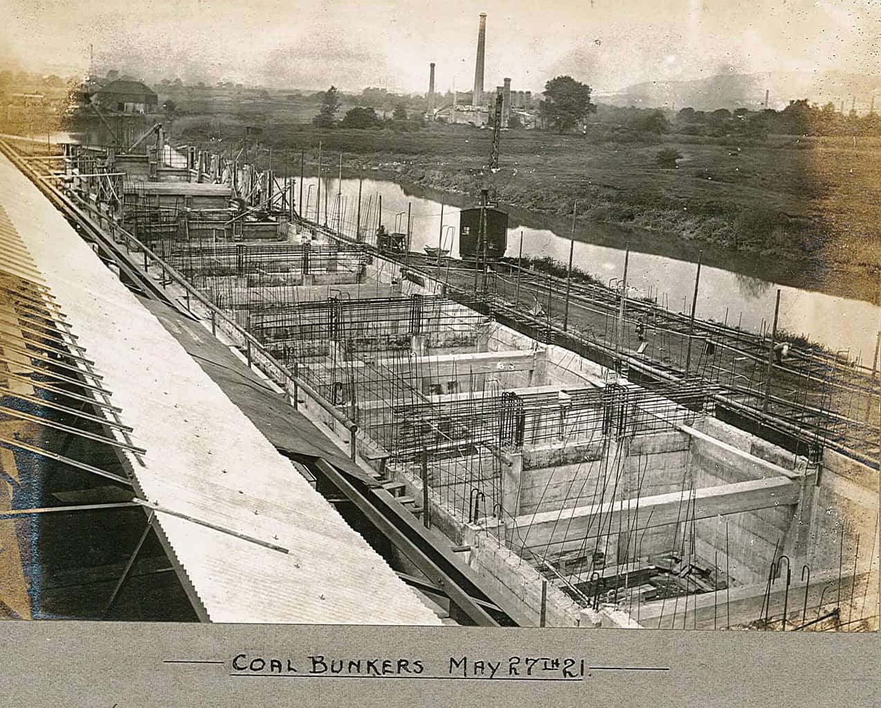
Participant67. Coal Bunkers.
The steam crane is engaged in cutting back the river bank to the wharf wall, spoil is carried away in the tipper skips to fill in around the Ferry House Inn.
Attachments:
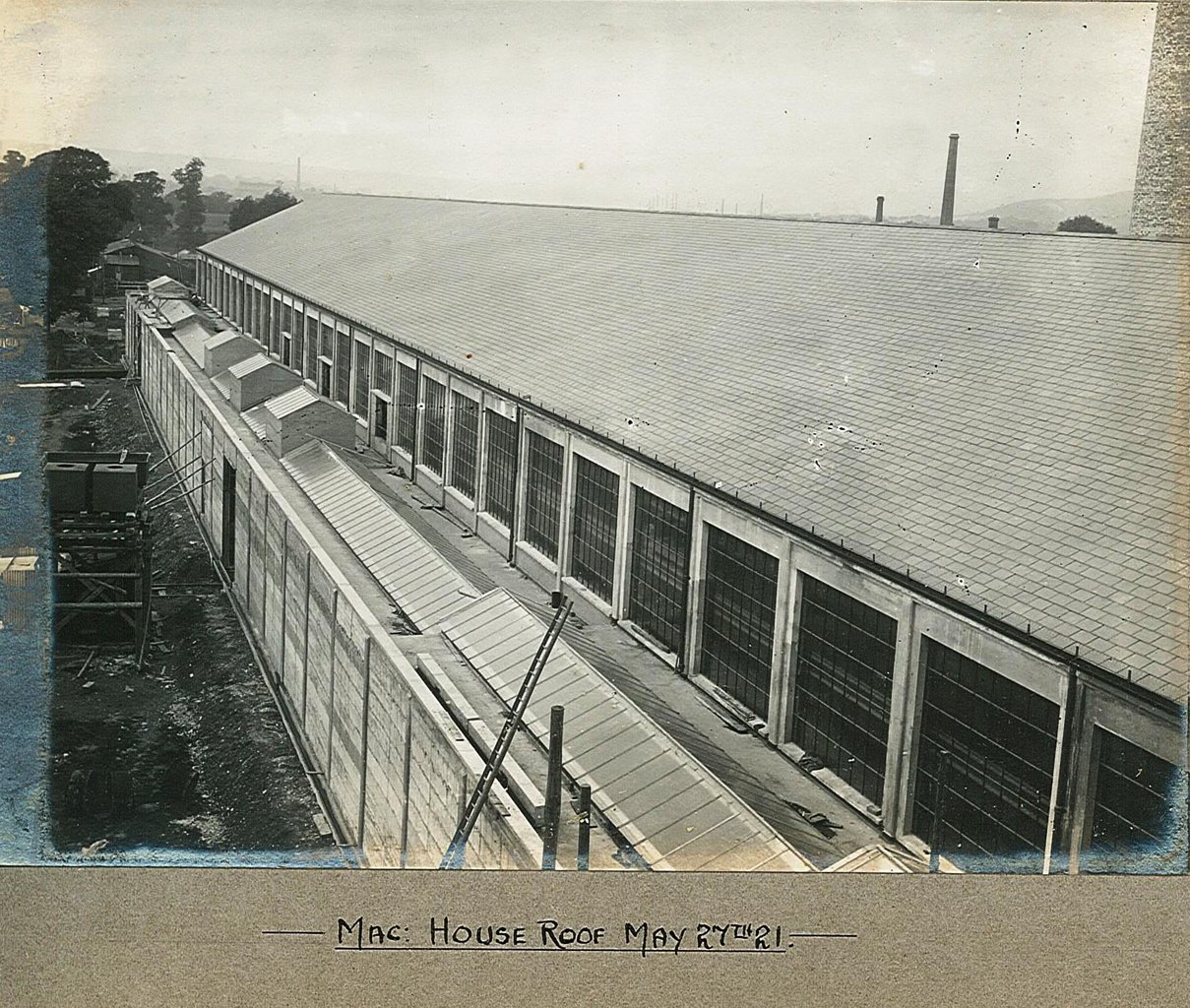
Participant66. Machine House roof.
Attachments:
Participant65. Boilerhouse roof.
A view northwards, down river, with the moribund Aylesford works of the West Kent Portland Cement Co immediately on the other side of the river, by the creek remnants of the river bends which defined the later island site. Further away is the works of the Burham Brick Lime and Cement Co, originally set up by Thomas Cubitt.
The boiler house roof is typically of fireproof construction, being corrugated iron sheeting directly on the steel framework, contrasting to the slates on wooden sheathing used for the beaterhouse and machine house.
Attachments:
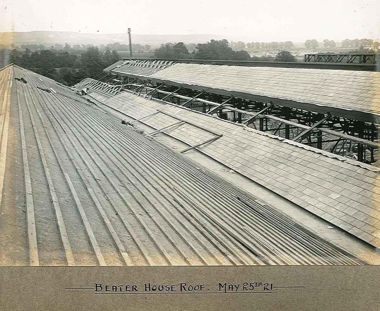
Participant64. Beaterhouse roof.
Looking east across the river towards the downs, the chalk quarries around Bluebell Hill are visible, and just across the river, the sand pits of Aylesford Sand and Gravel, and an area later used for the Maidstone sewage treatment works. Notable on the right is part of no 1 pulp conveyor structure.
Attachments:
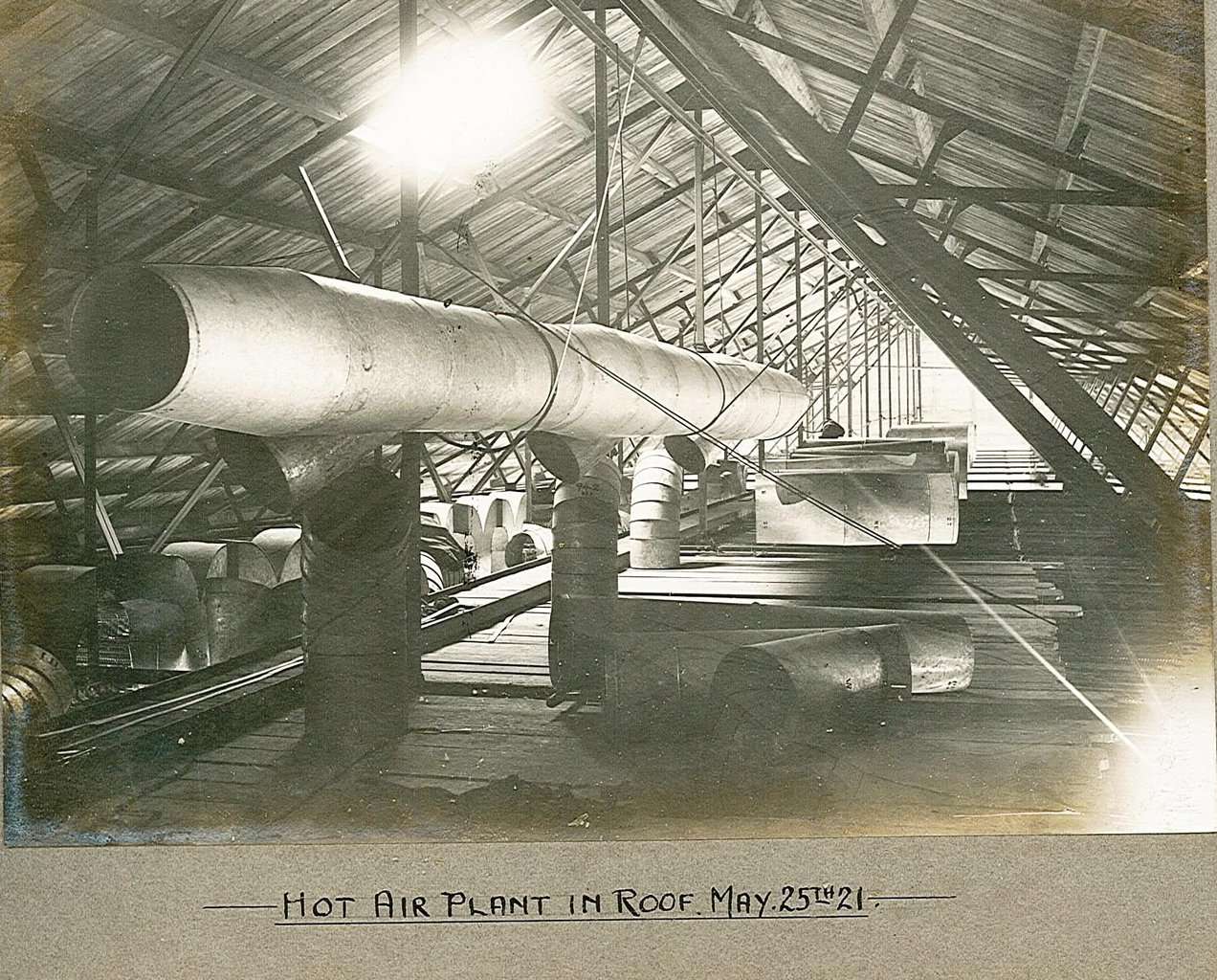
Participant63. Hot air plant in roof.
This is the ducting for supplying hot air to the underside of the ceiling to prevent condensation dripping – potentially drips woulf disrupt the formation on the wire. I think this is a view south from memory of a couple of excursions into the roof when we installed insulation (some sort of shredded fibre material) in the early ’80s. The narrow walkway down the centre is visible, and was all that was present in the ’80s. The planking under the duct pieces is probably temporary during the installation, it was not present later. Access to the lamps in the ceiling was quite precarious I recall, the electricians had to inch their way out along the roof trusses to reach the lamp housings.
Attachments:
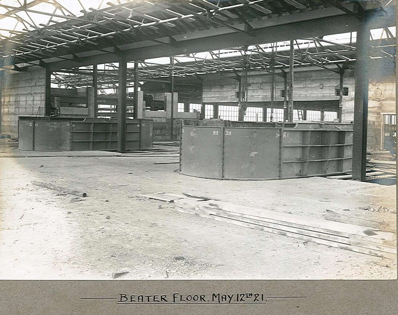
Participant62. Beaterfloor.
This is the upper level of the beaterfloor, looking roughly north west away from the river, through the incomplete wall can be seen the south end of the machine house, and over to the left, the end of the turbine house. Two pulp breaker tubs are in place. Gaps in the floor may be for the belt drive to come up from the mainshaft in the lower level.
Attachments:
-
AuthorPosts