Forum Replies Created
-
AuthorPosts
-
Artless Bodger
ParticipantNo 7. Over she goes! The boiler rolled off into the gateway.
View towards Upper Tovil mill and the foot of Tovil and Farleigh hills.
 Participant
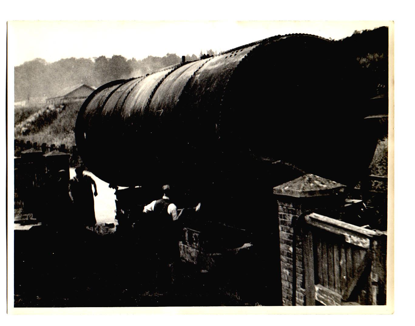
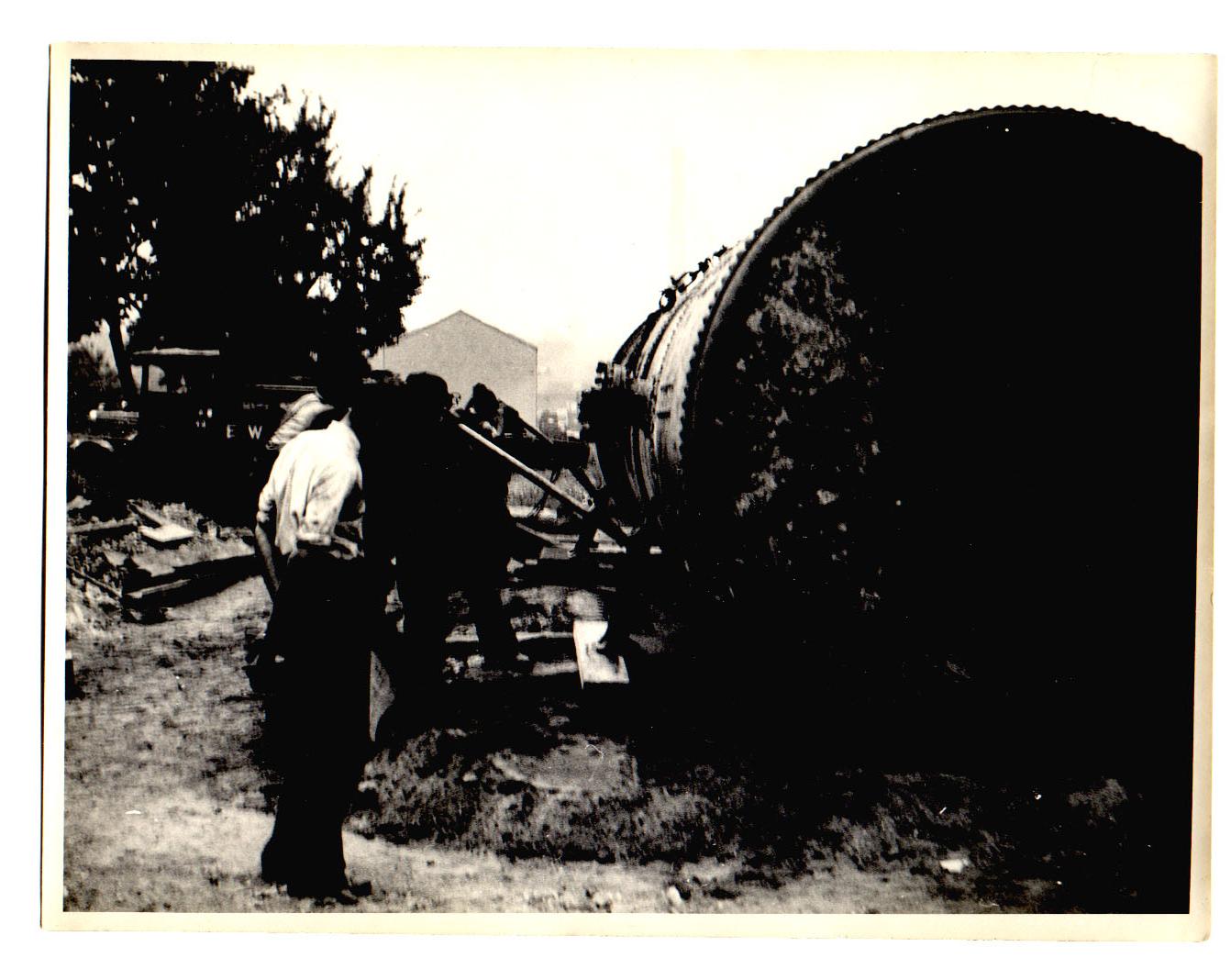
No 6. Arrived at the gate to the back of Lower Tovil mill (the main, front entrance was in Lower Tovil). The workmen are preparing to unload, knocking out wedges – looks a bit hazardous. The roof in the background is that of the goods shed (covered loading platform in fact) in Tovil Goods yard, terminus of the Tovil goods branch but at one time potentially an end on connection with the proposed Maidstone and Headcorn Railway which would have climbed the Loose Valley.
 Participant
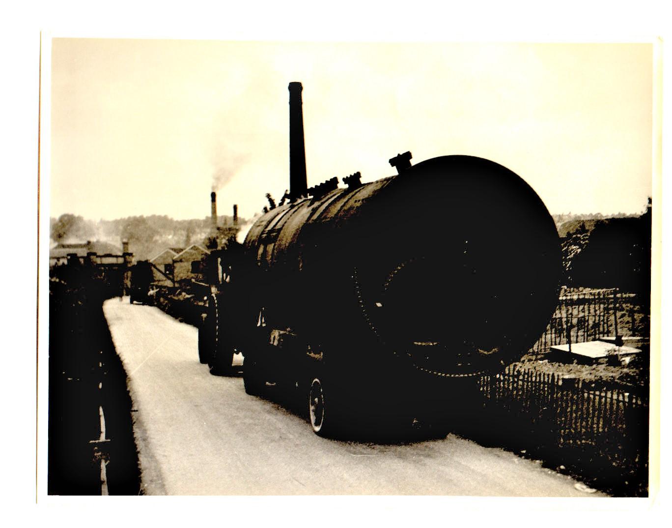
5. Another, wider, view of the boiler in transit, the smaller chimneys in the distance are Bridge Mill (Diamond Fibre, later Reed’s Bridge Mill), the houses visible beyond are the other side of the Medway in Fant, rising to the Tonbridge Road.
NB probably 4 and 5 should be transposed in sequence.
 Participant
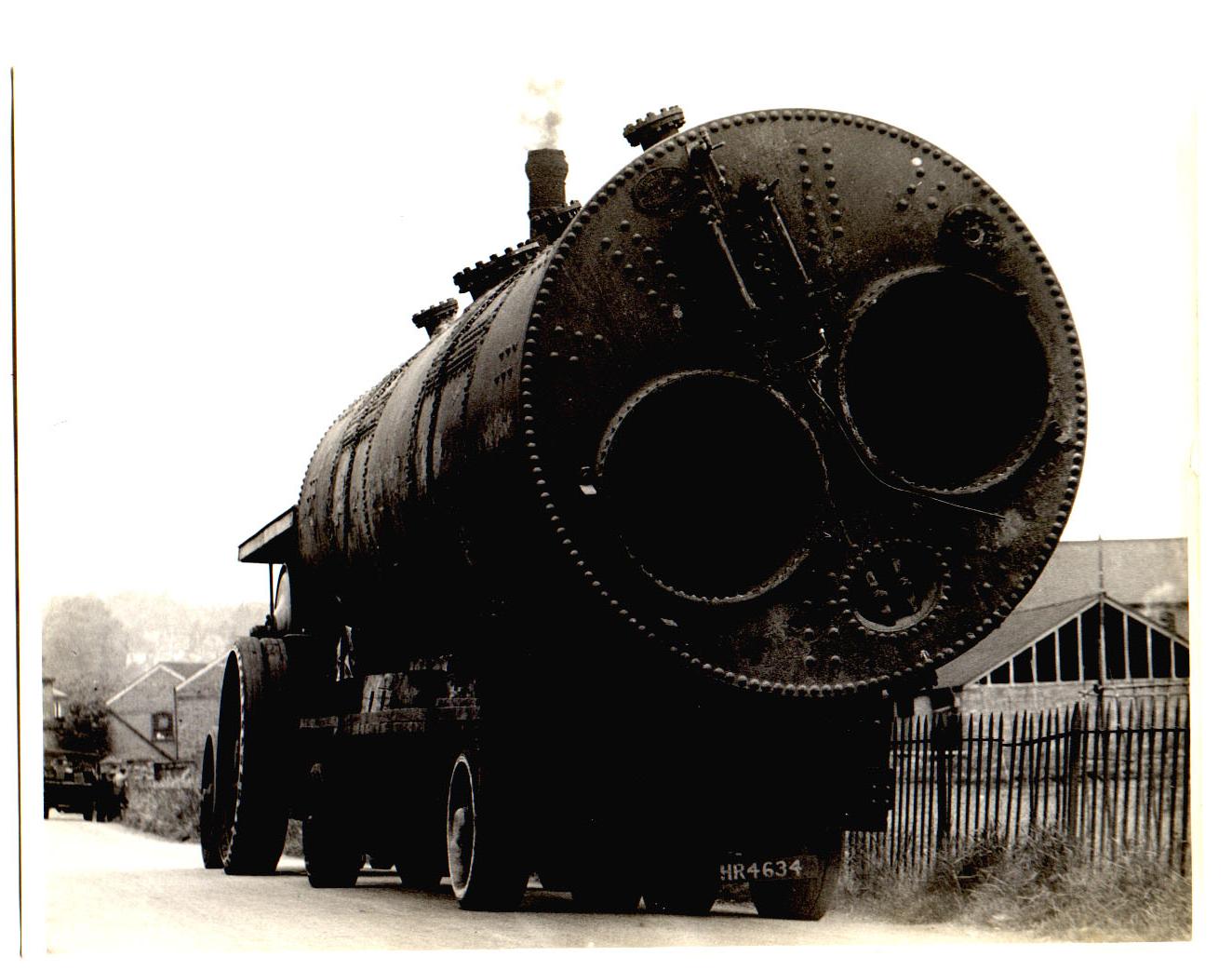
4. In transit, looking towards the river, buildings and chimney of Lower Tovil mill (Allnutt’s) behind the ensemble.
 Participant
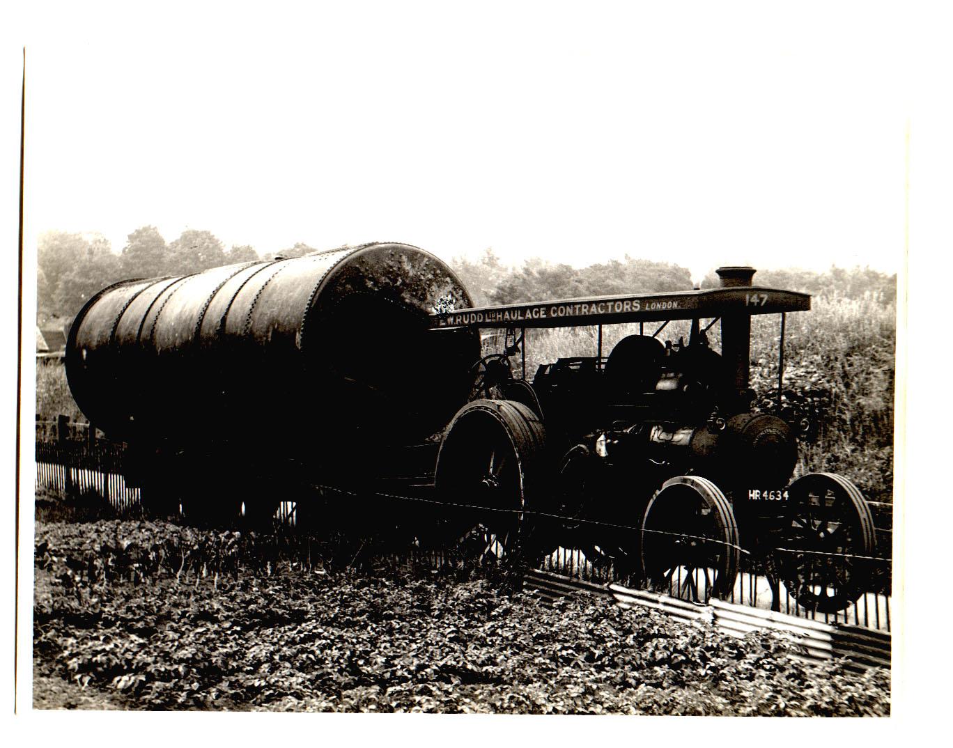
3. Ready to move down the lane.
 Participant
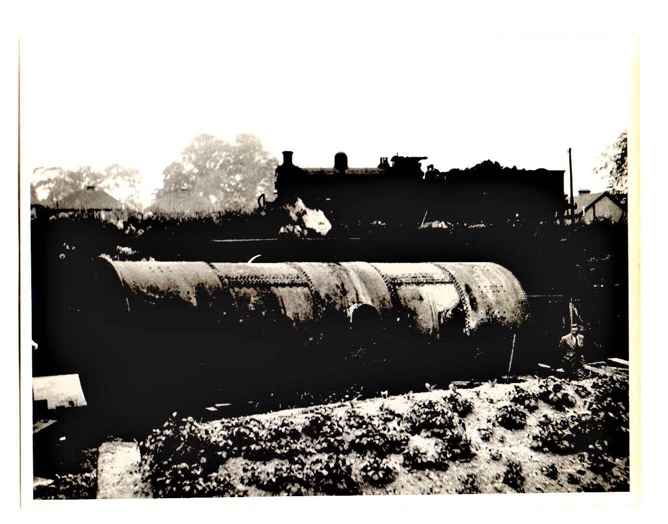
No 2. Winching and jacking the boiler onto the road trailer, shackles on the winch cables from the traction engine visible on the boiler shell, jacks and packing to the left. View is towards the bottom of Tovil Hill and Upper Tovil mill (Reeds). The corrugated iron shed visible is part of what was, or became RCC Tovil.
 Participant
No 1. Boiler on the lane, ready to be loaded onto road transport, the Tovil goods branch embankment behind and allotments in the foreground.
-
This reply was modified 4 years ago by
Artless Bodger.
ParticipantI have recently re-discovered some poor quality scans of family photographs recording the delivery of a new Lancashire boiler to Lower Tovil Mill – Allnutt’s.
The original photos were rather dark and the scans were hurriedly done (one dinnertime at work) with no attempt to adjust the settings. The photos went with other house contents after my mother’s death. I recall they had a stamp on the rear for the Maidstone photographer Sweatman Hedgeland who were down near the cannon.
I attach the photos for what they are worth. The new (maybe second hand?) boiler was delivered sometime in the 1930s – in the original photo it was just descernibe that the steam engine in one view had a 4 digit number beginning with 1 – so post 1931 Southern Railway renumbering scheme. I think I have got the order of the phots correct, the sequence shows the boiler, unloaded from rail transport (presumably rolled down the embankment from the goods yard), loading onto road trailer then drawn along the lane now called Allnutt Mill Close / Albert Reed Gardens. This move was only a short distance before the boiler was rolled off the trailer and winched in through the rear gate to the mill. The final photos show preparation of the boiler bed and it being dragged into position.
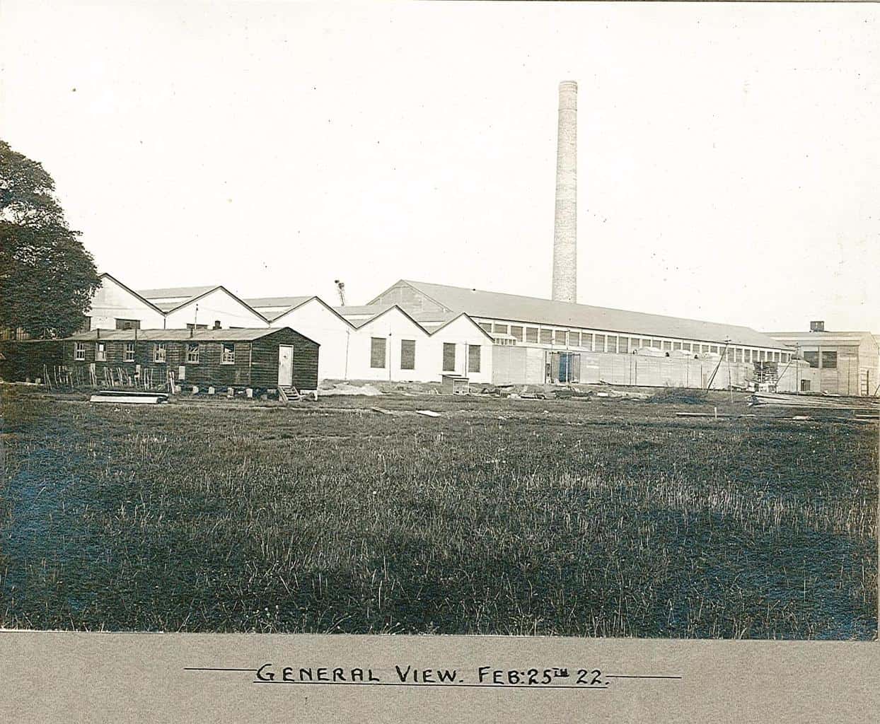
Participant125. General View, Feb 25, 1922.
The photographer must be standing with their back almost to New Hythe Lane level crossing. The temporary standard gauge siding to bring the machine parts into the end of the machine house can be seen rising centre left, to the opening left in the machine house wall.
That’s all folks!
But, some drawings will be provided later (too big to attach here). Also there are some photos taken during east mill demolition which I may post if there is sufficient interest.
Attachments:
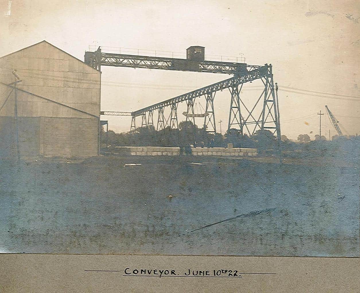
Participant124. Conveyor, June 1922.
Pulp stacks being built, the temporary corrugated iron upper wall to the powerhouse and beaterfloor range on the left, later opened up when the powerhouse was extended and the kraft beaterfloor constructed.
Attachments:
Participant123. No 2 Machine, May 1922.
Nearing completion, the deckle straps are in place, breast box under construction and the base for the 3 Fulner filters on the thin stock approach. This is much different to no 2’s condition when I knew it in the late ’70s – early ’80s. The breast box is low with less hydraulic head than it had later, so the machine speed would be relatively low (iirc it could do around 300mpm in the ’80s, i.e. around 9-10 tph at 125gsm). Six Fulner filters on the floor, 3 for each of nos 1 and 2. No 1’s eirw frame and table roll ends just visible lower RH corner.
Attachments:
Participant122. Salle, Feb 1922.
This photo was taken from a position roughly in line with the future New Hythe Halt behind the photographer. The mill siding is visible in the foreground, such as it was then, later No 6 loading dock would occupy this area. The wooden huts and trees are those seen in the flood photos.
-
This reply was modified 4 years, 8 months ago by
Attachments:
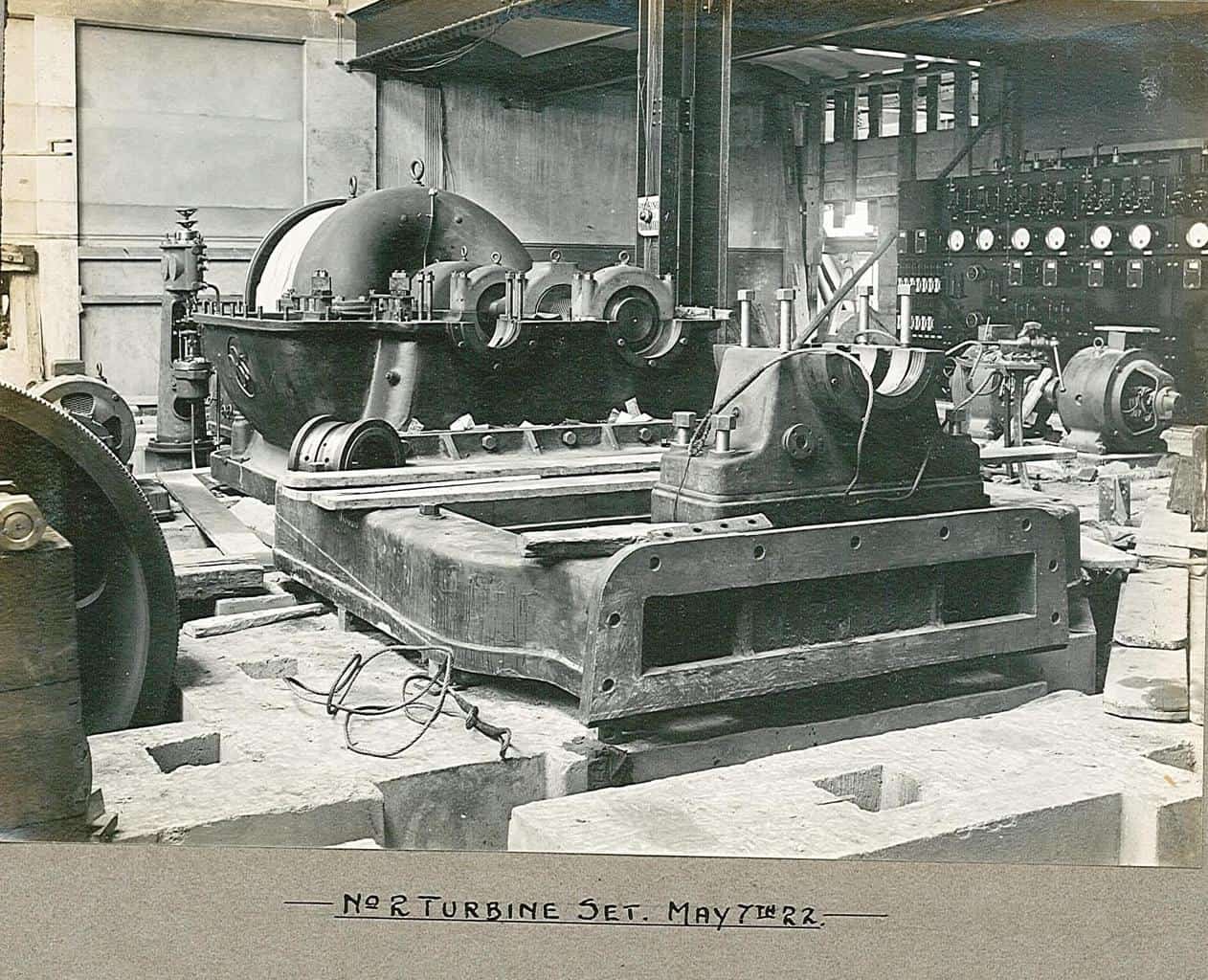
Participant121. No 2 Turbine Set.
The trubine is in place – the curved casing at the back, the steam control valve stand to its left. The open casing is for the reduction gearing, 3600 rpm to 428 rpm, to drive the generator (DC 400V) which would be installed on the cast bed frame centre. The gear casing has DBS – David Brown and Sons of Huddersfield, cast on it. In front of the genrator an extension drive shaft to a further reduction gearbox to reduce the speed to 150 rpm for the main shaft. The main shaft would pass through the sqaure hole in the wall, just visible top left, to the white beaterfloor basement. To the extreme left is visible a gear, probably part of the no 1 turbine set reduction gear to the main shaft. The turbines and generators stood side by side but the final drives to the main shaft were offset, see drawing AX107.
Attachments:
Participant120. Main Drive Shaft.
This is the eastern section under the white beaterfloor, another shaft ran from the powerhouse under the kraft beaterfloor as the mill was extended, and can be seen in some of the mill plans. By the late 1970s the white beaterfloor basement had been extensively rebuilt aand no sign of the main shaft remained. Some support piers of the western section remained under the kraft beaterfloor near chests Y1 – Y4 (the vertical cylindrical chests then serving no 3 m/c and as a starch slurry tank). The underside of the upperfloor of the beaterfloors showed the arrangement of the steel beams to provide for the drive belts to pass through to the refiners and beaters.
Attachments:
Participant119. Switchboard.
This is located in the powerhouse, as seen in the background of photo 121.
Attachments:
-
This reply was modified 4 years ago by
-
AuthorPosts