Forum Replies Created
-
AuthorPosts
-
Artless Bodger
ParticipantPhoto 5. A closer view of the roofless tunnel and the no 2 machine vacuum pump pit (ex no 1 mc press area).
Attachments:
ParticipantPhoto 4
Attachments:
ParticipantPhoto 3
Attachments:
ParticipantPhoto 2
Attachments:
ParticipantI hope these pictures will be of interest to Mike Presneill.
Photographs of no 2 machine in its last days and being demolished.
1. 2 mc last days in production. Visible on the right are the vacuum pumps in old 1 mc wire pit / press area. The blue pump and hoses suggest there may have been a problem with the hogpit pump.
2. Partly dismantled, wet end and vacuum pumps gone, the silo visible in the bottom right hand corner.
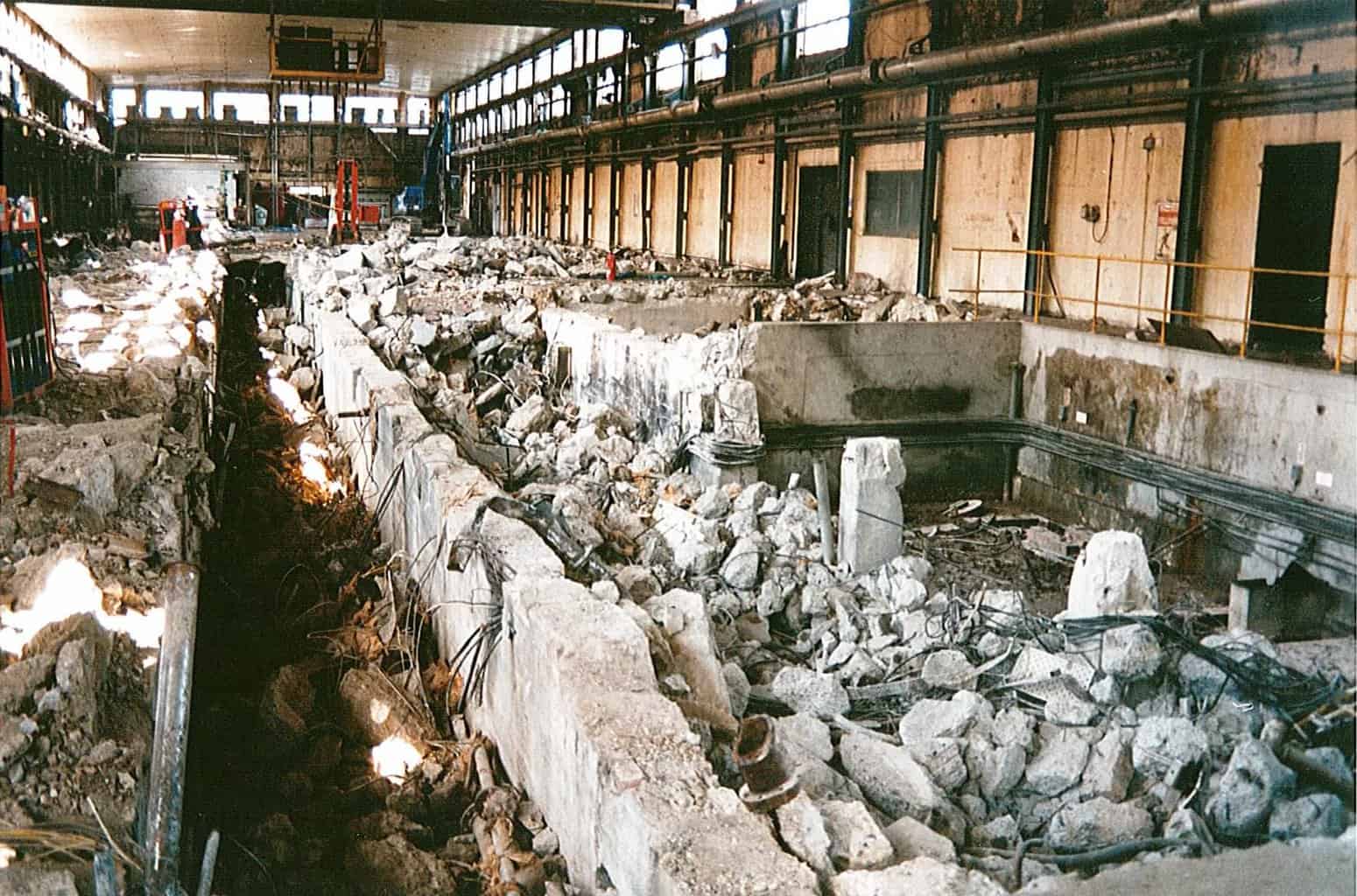
3. Last few cylinders of dryer 3rd section still in place, the hood over the 4th section after dryers still intact. The oily wasteland of the under felt is clearly visible.
4. All the metalwork has been removed and the concrete is being broken up (I think that basement was filled in and the floor made good so the machine house could be used as a warehouse for a few years). The tunnel along the machine basement is now opened up, compare this with photos during construction in 1921.
Attachments:
ParticipantI have been spreading bags of manure on the garden this afternoon and the smell reminded me strongly of the island site in summer, especially around by no 4 asp secondary clarifier if sludge had overflowed. This prompted a revisit to this site.
Regarding the island site and no 4 plant in particular, this was installed to handle the extra effluent when no 2 machine was converted to make fluting (later liner too). The new plant consisted of a prep plant to the east of the existing plants (3, 6A and 6B). The pulper was a side entry agitator Voith type (similar to the phase 2 de-ink plant hydrapulper). I don’t remember too much about the rest of the plant (cleaners etc) but recall the side entry agitators were prone to blocking up if baling wires were not all assiduously removed before bales of waste entered the pulper. No 2 plant was built at a slightly higher elevation than the others so the basement floor was usually dry, it also remained much cleaner that the earlier plants.
Outside, the effluent plant, comprised a deep sump and adjacent pump pit housing (I think) 3 pumps. The top of the sump was always covered by a thick crust of froth, fibre and plastic – mainly polystyrene packaging. The pumps fed no 4 asp primary clarifier – this was supplied by Portals Water Treatment Ltd (head office in Maidenhead, near my later place of employment). It was unusual in that the sludge extraction pumps were mounted on the rotating scraper bridge with their suction pipes led straight down into the centre anulus of the tank. This at least avoided the long suction lines found under the base of many of the other clarifiers – very prone to blockage by thick sludge. Water from the primary was fed to the rectangular concrete asp tank (maybe via the concrete lined lagoon – my memory is hazy on this). The asp tank was aerated by two large paddles. Recycled activated sludge was returned via a concrete flume down one side of the tank. After treatment the cloudy water was drawn off to the secondary clarifier, sludge drawn off at low solids by two Archimedean screws and lifted up for either return to the asp or to be mixed with other sludges before dewatering on the Paxman filters (the centrifuges had long gone by my time). The Paxman filters were later replaced by Tassters, after my involvement with the water and effluent plant. The clean water from the secondary clarifier always looked the clearest of the island site, unless the sludge was bulking. Peter West was the mill chemist most involved with the monitoring and control of the island site asps at this time.
Regarding no 2 machine supply, after the closure of no 6, liner production was switched to no 2, which used 6B prep plant (with its hot dispersion unit for the liner supply). No 3 plant was shut and 6A supplied no 3 machine. However, I recall that a fractionator was later installed on 6A plant and this perhaps was for liner stock, so I may have the use of 6A and B mixed up. Certainly towards the end of my time (c.1985) the old 3 plant and 2 plant were out of use.
Of the Paxman filters; there were 5 in all, 1-3 in the ‘Paxman House’ and 4 & 5 in the ‘Centrifuge House’. No 4 was originally belt discharge, the others string discharge, 4 was later converted after a period out of use – iirc the belt was prone to running off and difficult to clean. Dewatered sludge from either building was carried by conveyor to the gap between them, then led out to ‘jet throwers’ high speed conveyor belts with top nip rolls which ejected the sludge cake about 20′ into a partly enclosed area, whence it was shovelled up and loaded into a tip up lorry for dumping at Margett’s Pit (on the edge of the downs near Scarborough Terrace). Seagulls were often attracted to the piles of sludge and remarkably on one occasion I saw one ‘shot down’ as it were by a piece of cake flying from the jet thrower. It did not seem to be harmed however, just stunned and shortly got up and flew off.
ParticipantWas this the mill which also made flong?
I recall reading an article somewhere, which described the process of making and using flong for stereotypes, and included the words of the ‘flong song’ which I’ve been unable to uncover on the web. It was sung to the hymn tune – “We fling the flong and scatter the dry* flong on the…. etc”
*or wet, can’t remember which.
Cheers
ParticipantAn interesting point about Turkey Mill was its proximity to the Otford – Ashford railway line that was on a steep gradient at that point, the viaduct carrying the line over the approach road off the A20 was provided with tall side walls and a roof to prevent sparks and smuts from hard working steam engines from afflicting the mill. The roof was removed, presumably when the railway was electrified in 1962, and later the side walls cut down and replaced by metal railings when the Eurostar trains started to use the line as a diversionary route.
There was a short siding off the up line on the Maidstone side of the viaduct, with a sort of chute on wheels next to it, visible from both the trains and also from Mote Park. I never saw any wagons in the siding but would like to know if it was for unloading coal into a cart to feed the mill?
The stone wall along the southern boundary of the mill with Mote Park was relatively low at one point and on the mill side was a short wooden ladder. It appeared to be a short cut for employees living on the Foster Clarke estate, saving a long walk via Square Hill and Mote Avenue. As children we used to clamber up and walk along the top of the wall – one or two more adventurous souls went down the ladder and off down the path beyond, but as the mill was still in use and noises emanating from the building just beyond the undergrowth most of us stayed out!
ParticipantI think this loco was saved by a local school boy who donated it to the NRM, there was a newspaper story about it. It would have been worth less as scrap than a conventional steam engine as it had no copper firebox or boiler tubes. Strange that APM didn’t use fireless locos. More photos of Imperial’s railway are to be found on Flickr.
I visited Imperial with Jim Martin and the EM mechanical engineer (unfortunately I cannot remember his name) after the mill had closed, looking to see if anything was worth salvaging, but most had already been taken out. I think Imperial no 7 was a twin to APM no 13 and there were rumours no 7 would be rebuilt alongside no 13, as the m/c house seemed to be designed for a second machine (though the control room etc, reeler and supercalender would need to be resited. The corrugated end wall always seemed a bit temporary.
ParticipantRegarding the photos:
My understanding is that initially no 1 and no 2 made newsprint (as had Albert Reed’s earlier mill at Tovil), the beaterfloor part nearest the river (as seen in the photos of construction) was known in my day to old hands as the ‘white beaterfloor’ and one plan and photos show breakers for pulp, and then jordans for refining driven by belts from the mainshaft below. The kraft beater floor was initially the other side (west) of the power house – the mainshaft drive extended both ways. Both beaterfloors were rebuilt at intervals – there was no indication of the mainshaft under the white beaterfloor in my time, hydrapulpers had been installed (one remained, the other I assume taken out when Staper was constructed). I think the chests here were Z1 and Z2.
However at some point they also made kraft papers – probably because they were too small and slow for newsprint, especially after 9 and 13 were built. I remember reading a report on a fibre mass balance carried out on 1 when making black kraft.
The construction photos show bird screens on both 1 and 2 stock approach, by the 70s only no 12 had bird screens, all the other machines had pressure screens. This suggests no 2 wet end and breast box were rebuilt further south to lengthen the wire part when it was rebuilt for waste based furnishes, as the breast box was quite close to the machine chest.
The tunnel under the machine house (seen in some photos under construction), between the two machines, had a hole in the end wall about 2′-3′ square that you could wriggle through to access the turbine house basement and a steam pipe tunnel through to the area by the de-aerator and wet pits.
When 2 was rebuilt no 1 was taken out, part of its dryer pit was used for the new vacuum pumps, a new silo and fan pump were installed where 1’s breast box / wet end was, and the cyclone cleaners in the end of the old drive annexe, the rest of 1’s annexe was used mainly for electrical switch rooms for no 2. The new starch tanks for no 2 were placed in part of 1’s dry end basement. No 2 had a size press roughly where the original reel-up was, a new after dryer section and the old supercalender was swung through 90 degrees to become the machine calender frame. The end wall was opened up for a hoist to pass through to take machine reels to the new reeler, outside in the old salle. Additionally solvo pulpers were installed under the size press and reel up (there was a nasty accident when a crew member feeding broke down into the reel up solvo got his shoulders jammed between the floor and the building reel, he survived but had prominent skin graft scars). This area was later comprehensively guarded.
ParticipantSorry, wrong link, that’s the one with a few photos of wm stirling boiler house demolition.
The correct link for the 1 and 2 m/c photos is
ParticipantHello again
The photos I have are uploaded on
-
This reply was modified 6 years ago by
Artless Bodger. Reason: wrong link
ParticipantHello Chris
Another site you might like to link to is
Some of the photos appear to be of Colthrop, not Aylesford site.
Some captions also appear to be mis-identified too.
Regards, Artless.
ParticipantHi Chris
I remember seeing these samples at an evening do sponsored by Sandoz at the Royal Star Hotel in Maidstone. They also showed a film of the paper being made – people wearing shorts and flip flops carrying buckets of caustic soda solution to the pulping tank iirc!
ParticipantHello Michael Presneill.
You ask about 1 & 2 after 1971.
I had summer vac jobs from 1973 onwards until joining full time in 1975. The first summer I worked in Key Terrain offices but often met my father (in APM west) at dinnertime for a walk around the mill. 1 & 2 were both shut at that time, still with the supercalender and reeler in the machine house. 3 was already running fluting, with its reeler out in the old salle.
74 and 75 I worked in the centre dept, and 2 was being rebuilt I think in 75. In summer 76 I worked variously on no 3 and no 6 reeler and did a stint with another student helping on the starch plant (Staper was down and we were using bagged starch), during that time the conveyor belts to take reels from 3 and 2 reelers was being installed and no 2 reeler commissioned as we went over from no3 to do a trial run once. Summer 77 I was in the tech dept mainly west mill but occasionally went to east mill – travelling by train, if it was wet I’d go in 6 loading dock through the salle and up through either 2 or 3 m/c house through the beater floor (it was often flooded under no 6 wet end), over the pipe bridge and through west mill to get into the tech dept roof entrance, 2 was making fluting then. Later, 6 and 8 closed, 2 became the liner machine (125, 150 and 200 gsm single ply) and 3 stayed on fluting.
I have in front of me the commemorative mug: ‘Aylesford Paper Mills Record Output 2600 Tons w/e 17th Oct 1983 East Mill’ . We all got one in east mill (I was in EM tech dept then after the mill was split into 2 cost centres), that 2600 Tons was off 2 & 3 machines only. One reason we got the output up was by substituting bagged cationic starch in 2’s wet end allowing the sizepress to be bypassed and so increased the dryer capacity, we could get 2 up to 10 tph on the right grade (150gsm was the best balance of drainage and dryer limitations I recall), as long as the Island could keep up!
Happy Days! (Well in retrospect mainly).
-
AuthorPosts