Forum Replies Created
-
AuthorPosts
-
Artless Bodger
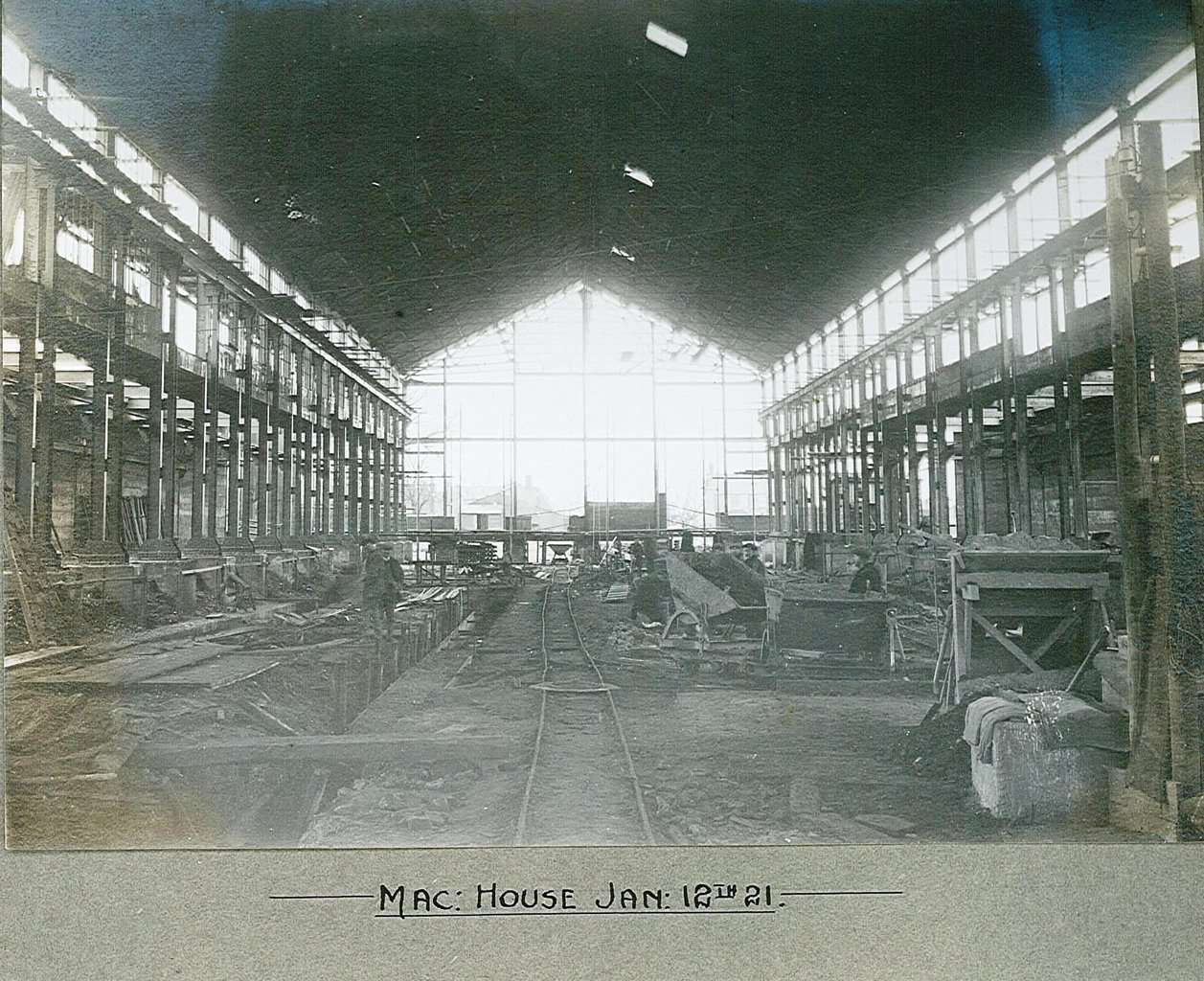
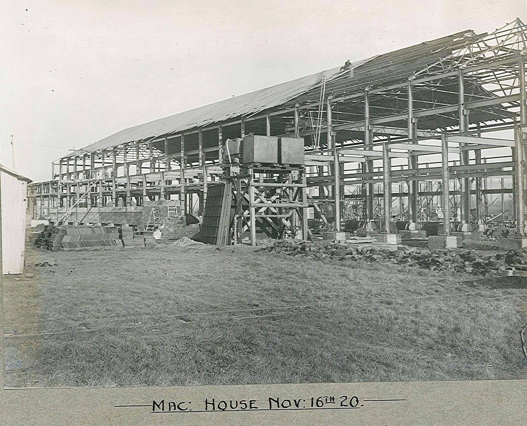
Participant23. Inside the machine house, looking south. The beater floor frame and floor joists are being erected. It is notable that the basement level is being excavated from the natural ground level down to install the floor at 8′ OD, but spoil is being retained to back fill between the machine pits to the 16′ OD floor level – this is clearer in later photos. From left to right there will be eventually; no 1mc pit, infill to floor level, pipe tunnel at 8′ OD, no 2mc pit. The tunnel connected at the south end through a square hole in the south wall to the pipe tunnel leading from the boiler house basement to the turbine house basement.
Attachments:
Participant22. Inside the machine house, looking north. The eventual machine floor level is evident from the horizontal concrete beam at the end, on which the north end walls are being cast. NG track in the future basement, with a turn plate in the foreground (to swivel wagons off the line onto spurs without installing points – turn plates could be moved to anywhere they were needed). The posts in the floor appear to be for the shuttering for the walls which will define the tunnel in the basement and support no 2mc soleplates.
Attachments:
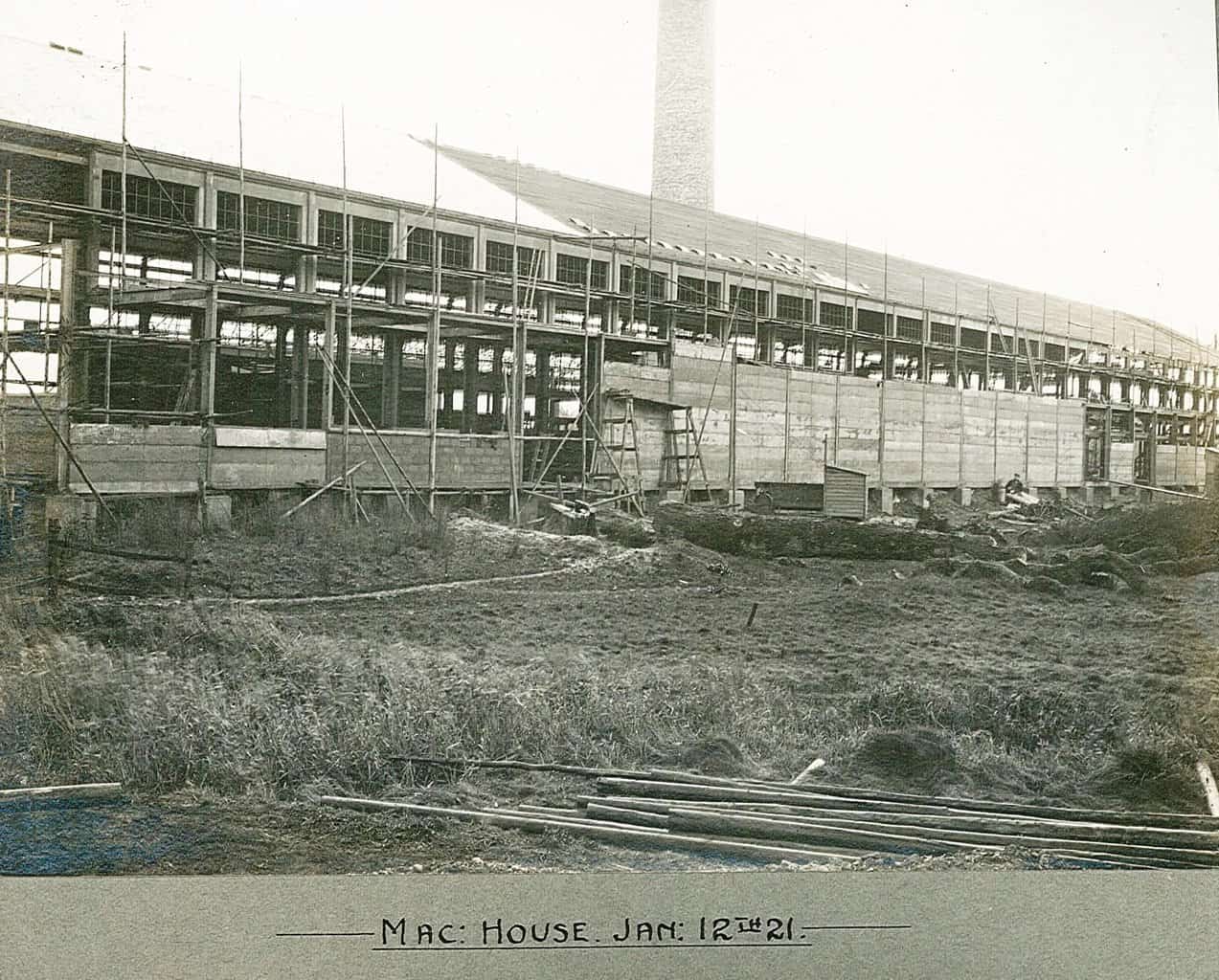
Participant21. Machine house taking shape, roof being slated. The natural ground level in the foreground is notably lower than the eventual machine house floor level.
Attachments:
Participant20. Chimney near completion. Temporary electricity supply going from horizontal to vertical over porcelain insulators in the foreground – probably for lighting in the wet pit excavation.
Attachments:
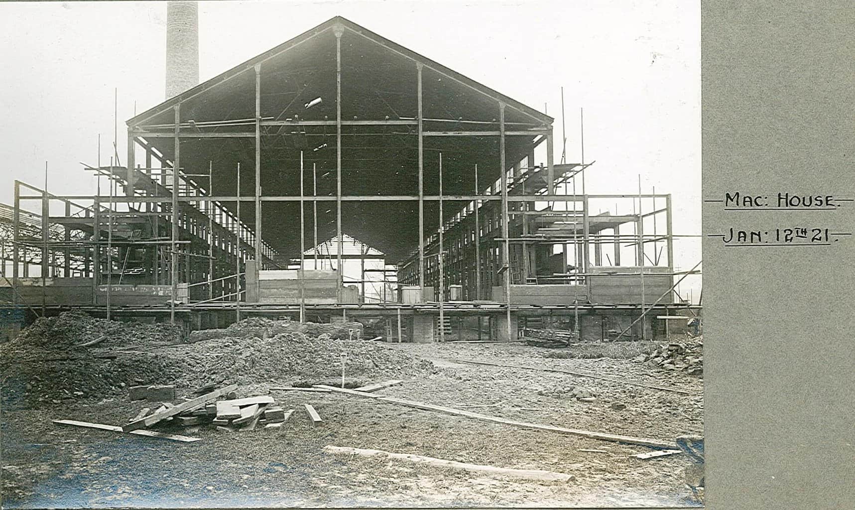
Participant19. Machine house north end (see boiler house to left). The machine floor level is evident and the basement under, a V skip just visible on a track in the basement. The scaffolding appears to be of wooden construction (tapered poles), not the metal tubing we see today (photos of the rebuilding of Cardiff General station in the 30s also has wooden scaffold poles).
Attachments:
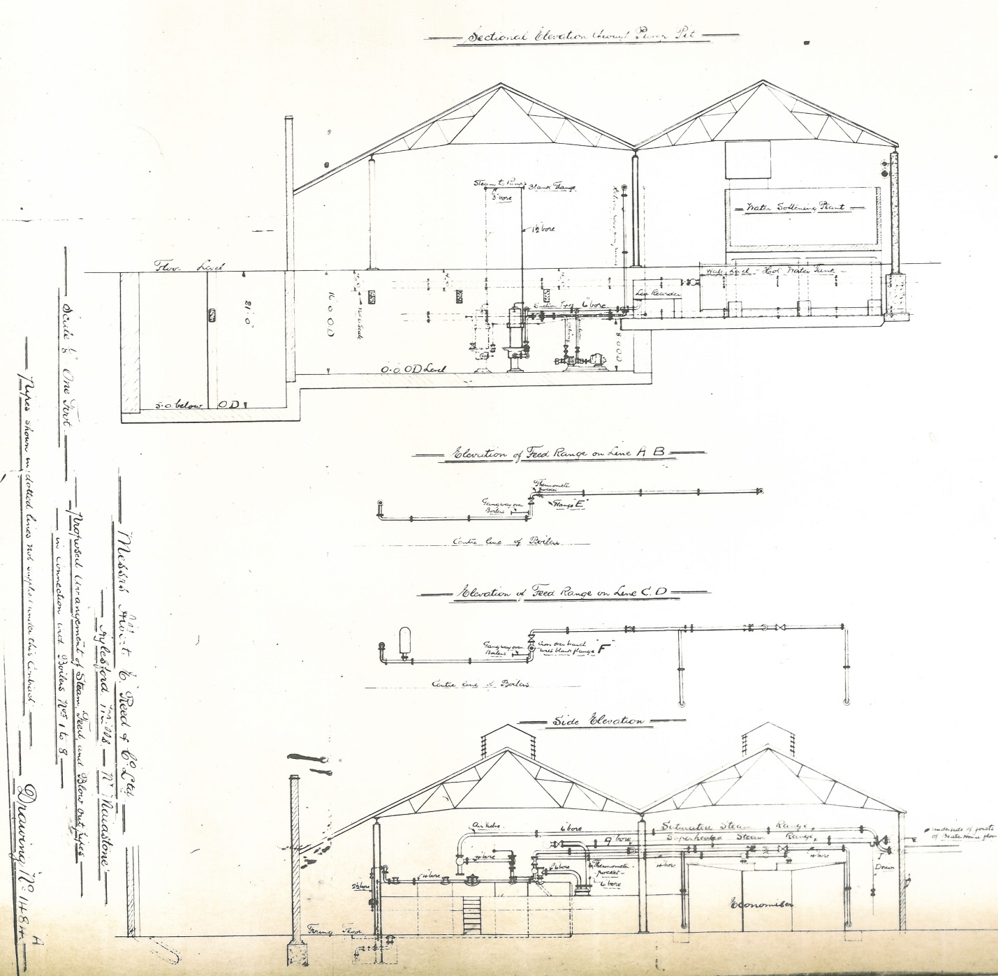
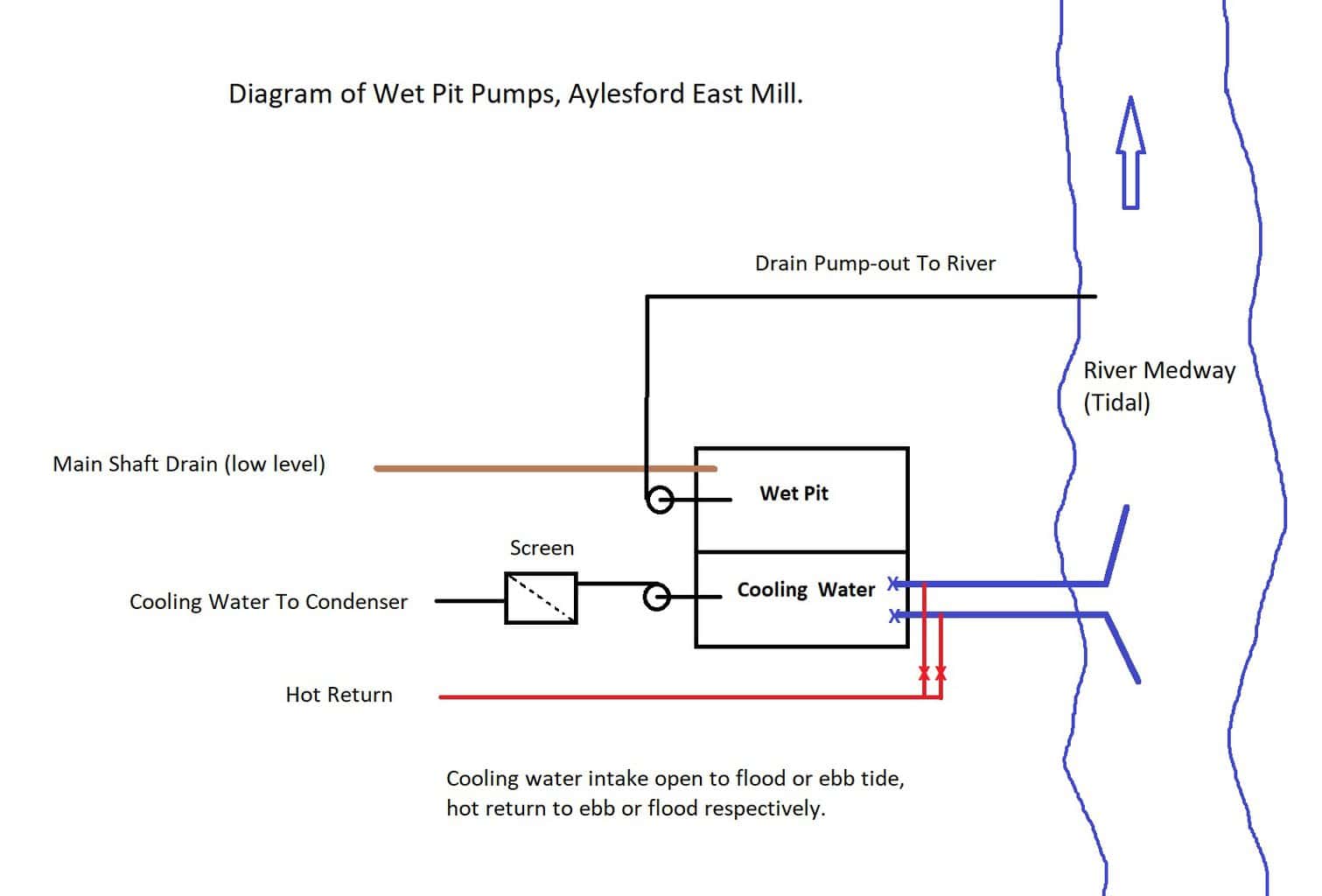
ParticipantWet Pit and condenser cooling water.
Here is a scan of a cross section drawing of the boiler house, showing the wet pits and details of the floor levels; main floor level 16′ OD, sub-basement (pump pit level) 0′ OD, wet pit floor -5′ OD.
A sketch of the original cooling water intake / discharge arrangement as I remember it from seeing drawings (over 30 years ago so I don’t guarantee accuracy), the valves to swap the intake / discharge according to the tide were operated from the platform over the cooling water pit.
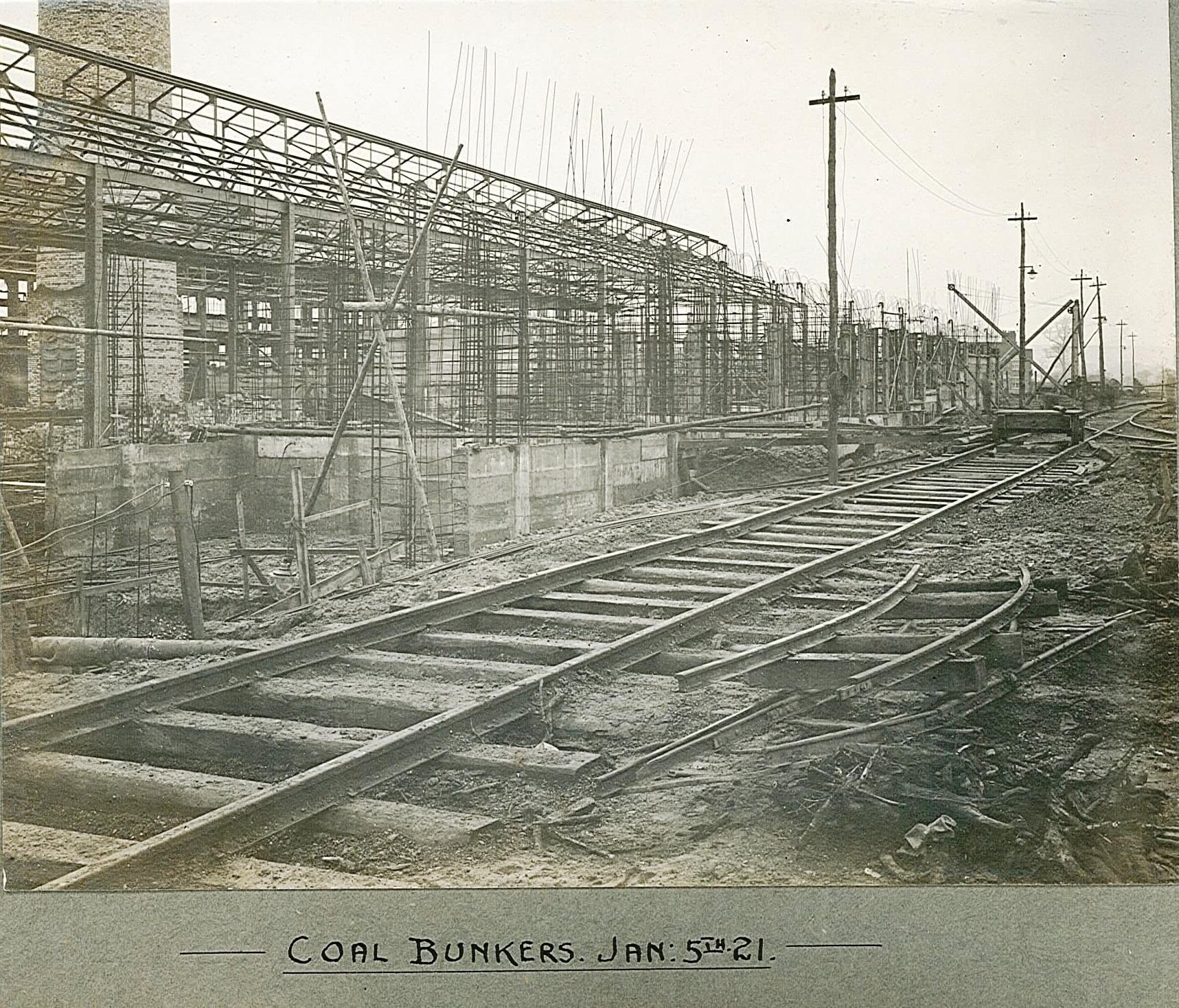
Participant18. Coal bunkers under construction. Oops! Enhanced version was too big, here’s the original (less clear) version.
-
This reply was modified 5 years, 5 months ago by
Artless Bodger. Reason: Spelling
Attachments:
Participant18. Coal bunkers under construction. This photo is a slight turn to the right from the last, the corner of the wet pit excavation is visible in the bottom left. The poles carrying the electricity supply are evident, including a low level one with wires leading over insulators into the wet pit. I’m assuming this is mainly for lighting as portable electric tools were not common at that time (though I stand ready to be corrected). Also I would not be surprised to find that the power was low voltage DC, maybe 50V? (Internal power in the mill later included 50V DC for portable equipment before the days when 110V AC became the standard).
The pipe emerging from the pit and crossing under the SG track is probably for dewatering the excavation, given the depth and gravel substrate here (when we did mud clearing in the ballast pit during mill shuts in the late 70s and early 80s though we pumped out most of the water with no5 reservoir pump, percolation through the gravel at high tide always partly refilled it. When the building dept dug a sump in the no 4mc basement to collect leaks and washings from no 3mc size press, the hole filled with water quite quickly due to rising tide).
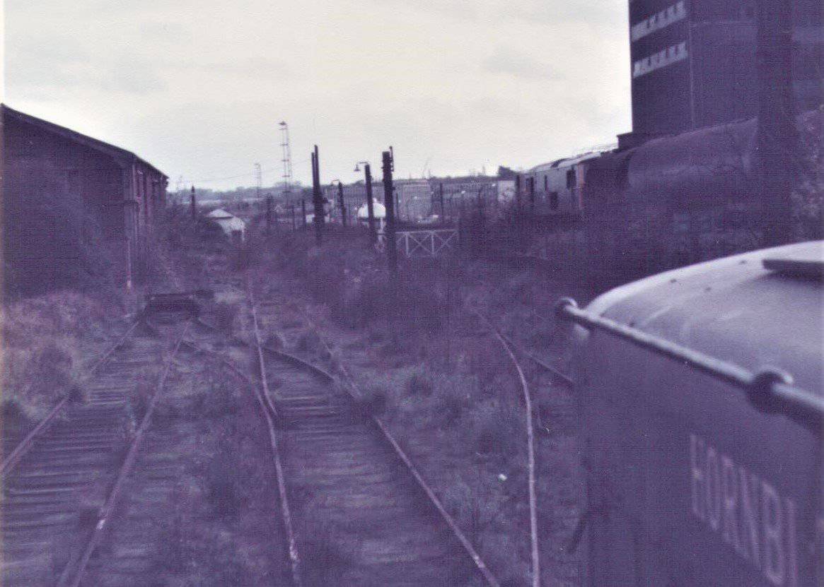
Standard gauge and narrow gauge track in evidence. As the NG in particular was moved around to suit the requirements of the building work, it was treated much like model railway sectional track, pick it up and lay it down where needed. The SG trolley visible in this photo (there were maybe more than 1), appears in later photos and looks remarkably like one which still existed in the early 80s by the water tower and east mill rail weigh bridge. It’s just about discernible in this rather poor photo I took as one of a series when we sent away the last chlorine tanker to be used on site.
Attachments:
Participant17. Beaterfloor foundations. The south end of the machine house on the right. The railway wagons are standing on the main mill siding parallel to the SECR mainline which runs along the embankment behind (prominent dark band) with the pale boundary fence posts in front of it. The main mill siding became one of the two eventually running from the connection near west mill drain pump house up to New Hythe Lane, passing under no 6 mc annexe and the beaterfloor on the way. This was where Bounty and later Hornblower would be stabled, visible from passing trains. New Hythe halt did not exist at this time, though the line from Maidstone to Strood had opened (by the SER) in 1856. A wooden halt was provided adjacent to the New Hythe Lane level crossing in 1929 to serve the mill, and was rebuilt to its current form (more or less) in time for the line to be electrified in 1939 (as part of the Maidstone and Gillingham electrification project).
One wagon is another Midland Railway open, the other appears to have either E R or L R visible on its side, I’ve tried enhancing the photo but cannot see clearly the first letter, E does not make sense, but if L then it could well be an LNWR low sided open, as one is visible inside the machine house during the installation of the papermachines.
Attachments:
Participant16. Boiler house roof
Attachments:
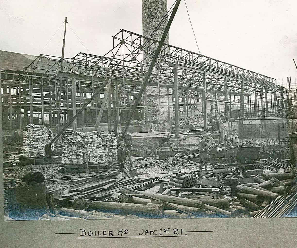
Participant15. Lancashire Boiler House under construction. This photo is full of interest, especially the excavation going on in the middle foreground, which is of the nascent wet pit comprising the turbine condenser cooling water supply pit and the effluent wet pit which collected from the mainshaft drain below the basement floors. Both wet pits went down to below the level of the river bed. The turbine condenser cooling water was taken from one of two pipes in the river bed, one facing upstream the other downstream, these were swapped according to the state of the tide, one for intake the other for discharge, the changeover controlled by valves operated from the metal floor over the pit. In my time this was too corroded to be safe to explore, with a possible 30+ foot drop into whatever water / mud remained in the pit. I had seen drawings relating to this original system in the drawing office. Later water intake was made at Medway pump house, and the cooling water supplied to a sump under the later electrical workshop in east mill adjacent to the turbine house, return water discharged into a tall collecting pot under a metal pent roof in the corner of no 1 conveyor. This pipework, though unused became the source of a funny story which I’ll relate at a later time. I have demolition pictures of the sump being broken open in the final days of the mill – having warned my brother that such a pit existed, as I did not know whether it was appreciated to be there by then.
The derrick has been ballasted securely with stacks of bricks, and appears to be being used to lower the V skip bodies into the wet pit to remove spoil. The two men at the base of the derrick jib appear to be wearing uniform, potentially army surplus, the man in the large cap, waist coat and leather gaiters is presumably the gaffer. The NG railway track crosses the wet pit excavation on way beams and has planks in the two-foot for pedestrians, as the skips are mainly hand propelled (though petrol locos appear in other photos). Coal bunkers in progress on the right. From the hook dangling in one of the frame openings it looks like 2mc annexe bridge crane is in situ.
Attachments:
Participant14. Coal bunkers in an early stage of building. The chimneys visible in the gap on the right are Burham Brick Lime and Cement works, the chimneys on the left visible through the forest of reinforcing rods are of the moribund West Kent Portland Cement works.
Attachments:
Participant13. Beater floor foundations, Burham cement works clearly visible in the background.
Attachments:
Participant12. Chimney nearing completion.
Attachments:
Participant11. Machine house roof going on.
Steel window frames stacked against the water tower with slates stacked nearby, annexe walls in progress with the shuttering in place for the next layer. These concrete walls were particularly tough to drill into, my brother commented on how many drill bits they broke when putting up cable trays during the rebuilds, mainly due to the flints from the ballast.
The manual bridge crane is in place in the machine house. The fortitude of the workers has to be admired, modern H&S would not tolerate the practices visible here. The ladders are not placed 4up – 1out.
Attachments:
-
AuthorPosts